USB Connectivity That Is So Very Very Small

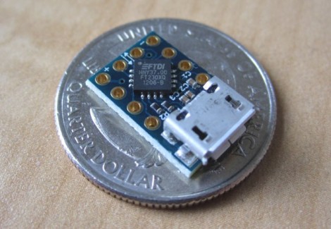
Using FTDI chips as a USB to Serial solution is nothing new, but this MicroFTX board takes the footprint to a new low. If you’re space limited this should have no problem fitting into your project. But if you plan to use it for prototyping we predict it’ll be lost in the parts bin forever as soon as you take your eyes off of it.

The USB Mini-B connector is becoming quite popular with hobby electronics these days. But here [Jim Paris] chose to use its little brother, the USB micro connector. Want to put this together by hand? How are you with 0402 footprints and QFN chips? In fact, there’s a ground pad on the bottom of that IC which means you really need to use a reflow oven to do the job right.

Aside from the diy-unfriendly fabrication size, we do like the design. There are four output pins (voltage, ground, TX, and RX) with a set of four solder jumpers to configure them. It can be powered from the USB port or an external connection, with the option for 5V or 3.3V output.

[Thanks John]

BB313 Breadboard Platform Makes ATtiny Prototyping Painless

Johngineer's BB313

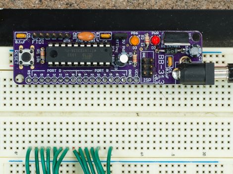
[John De Cristofaro aka Johngineer] uses various ATmega microcontrollers in his electronics projects, but he finds himself reaching for an ATtiny2313 or ATtiny4313 more often than not. He got tired of having to wire up pin headers, capacitors, and the like each time he started a project, so he spent some time designing an easy to use breadboard platform around the chips.

Inspired by LadyAda’s Boarduino, his BB313 board features FTDI pin headers, an ISP programming header, a reset button, along with breakout pins that plug directly into any breadboard. Aside from sharing a similar layout, [John] says that the similarities end there. His board is designed for designers who program in C or C++, so Arduino code won’t run without some substantial modification.

The board looks like a pretty handy benchtop tool, and we’re pretty sure it would be a big time saver for anyone who uses these chips with any frequency. [John] says that the board cost about $6.50 to make when he put it together, but that prices might vary slightly depending on where you have your PCBs made.

Be sure to swing by his site if the design looks like it might be helpful. He has made the schematics, a bill of materials, and all the rest available for the taking.

[via Adafruit blog]

FrankenKindle: Building An Alternate Kindle Keyboard

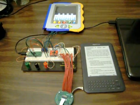
If you’ve ever thought the Kindle keyboard was a bit cramped you’re not alone. [Glenn’s] been working on developing an external keyboard for the Kindle for quite some time. It may not make easier for everyone to use, but he’s motivated to improve usability for his sister who has Cerebral Palsy.

We see a lot of keyboard hacks that solder straight to the pads under the buttons, but for a compact device like the Kindle this would really mess things up. Instead of going that route, [Glenn] sourced a 20-pin Flexible Flat Cable and breakout board that match the internal Kindle connector. The prototype seen above uses a TS3A5017 serial multiplexer chip to simulate the keyboard button presses. That multiplexer is driven by a Teensy++ microcontroller board which is monitoring a larger set of buttons on the V.Reader seen above. Check out the video after the break for a brief demonstration, then look around at the rest of [Glenn’s] blog posts to view different steps of the development cycle.

Continue reading “FrankenKindle: Building An Alternate Kindle Keyboard”

Reading NAND Flash Chips Without Removing Them

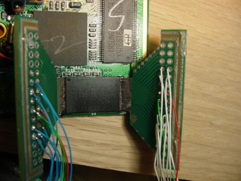
Here’s an interesting method of reading data off of a NAND flash chip. Often we see these chips desoldered in order to read and write data, but not this time. This method uses hacked adapters to match the pin pitch of the various chips. Above you see parts of a breakout board cut down to use as wedges. These are drag soldered to the pins of the chip, then the appropriate breakout pins were connected to a Smartmedia card reader, which can read NAND chips. There is also an example showing the flexible connector cable for a DVD rom used as the adapter to solder to a smaller chip. We still looks pretty tricky, but it might be less labor intensive than relocating the flash chip like we saw on that Sega Game Gear hack, as long as you only need to read or write the data once.

[Thanks Laurdy]

Touring The Available Nokia LCD Screens

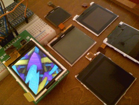
[Rossum’s] taking a look at the Nokia LCD screens that are both plentiful and begging to be bent to your will. For quite some time the Nokia 6100 screens have been used in a lot hacks, but he wanted to see what else is out there. He digs into his junk box of cell phones and comes up with a couple to test; the Nokia 6101 and Nokia 2760. The screens use a 3-wire SPI interface, which he sniffs out with a logic analyzer. At power-up the cellphone polls the screen to determine which type of LCD controller is connected. [Rossum] grabs these commands from the logic analyzer and uses it to determine the hardware in use with each screen.

He made himself a nice breakout board which has connectors for several different screens. The firmware he’s using detects when a screen is attached and switches to the applicable protocol for that display. Take a look at the video after the break.

Continue reading “Touring The Available Nokia LCD Screens”

Using An Arduino Or Seeeduino For Its FTDI Chip

We think of the Arduino as a rapid prototyping tool but we never thought of it as an FTDI breakout board before. [Ihsan Kehribar] wrote a quick post to show how it’s done. You’ll find an FTDI chip on Arduino boards that have a USB connector. It’s used to handle the USB communications on one side, and TTL serial communications on the other. The serial pins from the chip are mapped to the UART on the AVR chip, and in turn they appear on the pin headers for easy connections. Just load up a really simple sketch(available from Ihsan’s post) to make sure the processor doesn’t get in the way and you’ve got yourself an FTDI breakout board. If you happen to have a Seeeduino there’s even more functionality as the board has a selector switch that allows you to choose between 5V and 3.3V levels.

This doesn’t hold true to the newest generation of Arduino, as those board have replaced the FTDI chip with an ATmega8U2. That’s basically and ATmega8 with native USB handling… fancy.

[Thanks Marcus]

DS1307 Breakout Board

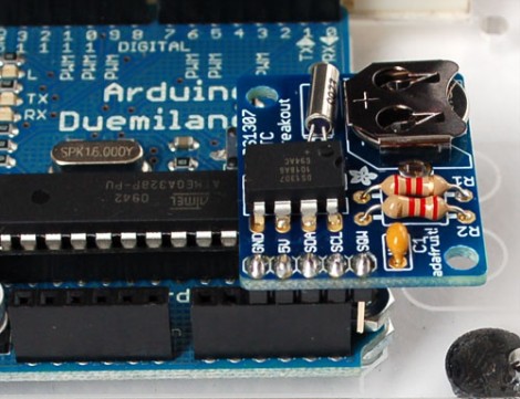
Adafruit’s got a handy breakout board for the DS1307 RTC available. This chip isn’t nearly as accurate as the DS3231 used in the Chronodot but it’s quite a bit cheaper. The breakout makes this easy to breadboard or plug into an Arduino and has everything you need; clock crystal, a backup battery, filtering capacitor, and pull-up resistors. Our favorite part is that Adafruit designs are open source so you can etch the board yourself if you checkout the files from their git repository. This will make a great addition to our prototyping hardware collection.

Incidentally, we were surprised to see the choice of 2.2k resistors for the I2C bus pull-ups. We were under the impression that 4.7k was a standard value here. We’d love to hear your thoughts on this in the comments.

[via Dangerous Prototypes]