Tiny PCB Motor Robot Is Making Its First Wobbly Moves

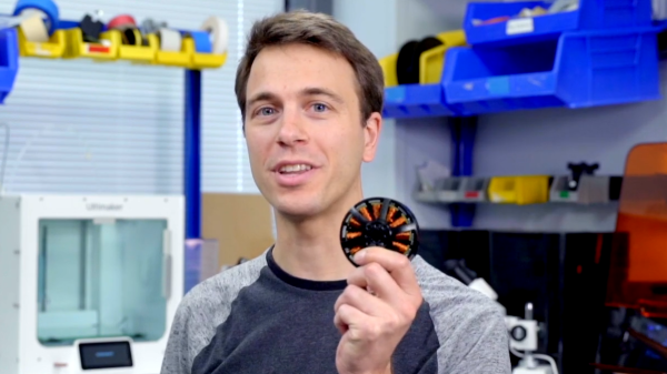
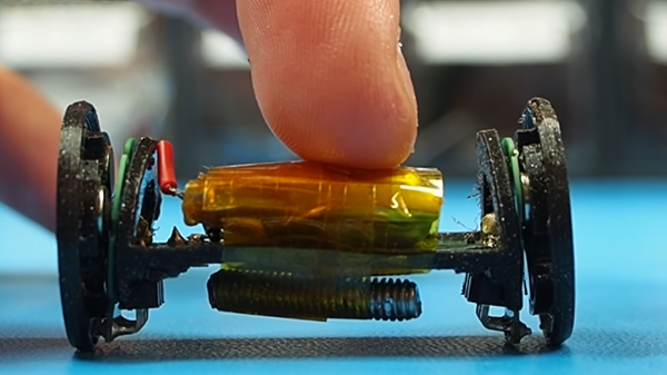
[Carl Bugeja] has been working on his PCB motors for more than three years now, and it doesn’t seem like he is close to running out of ideas for the project. His latest creation is a tiny Bluetooth-controlled robot built around two of these motors.

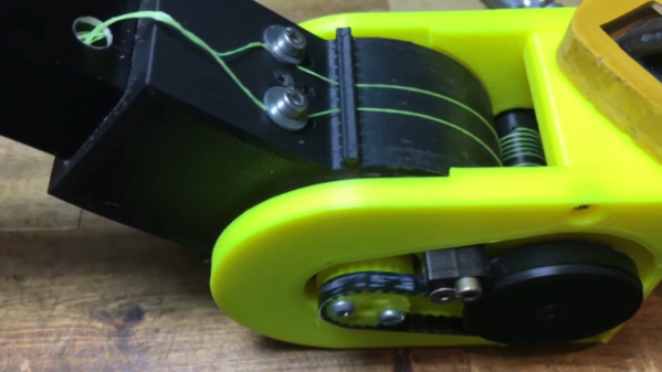
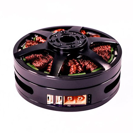
One of the main challenges of these axial flux PCB motors is their low torque output, so [Carl] had to make the robot as light as possible. The main board contains a microcontroller module with integrated Bluetooth, an IMU, regulator, and two motor drivers. The motor stator boards are soldered to the main board using 90° header pins. The frame for the body and the rotors for the motors are 3D printed. A set of four neodymium magnets and a bearing is press-fit into each rotor. The motor shafts are off-the-shelf PCB pins with one end soldered to the stator board. Power comes from a small single-cell lipo battery attached to the main board.

The robot moves, but with a jerking motion, and keeps making unintended turns. The primary cause of this seems to be the wobbly rotors, which mean that the output torque fluctuates throughout the rotation of the motor. Since there are only two points of contact to the ground, only the weight of the board and battery is preventing the central part from rotating with the motors. This doesn’t look like it’s quite enough, so [Carl] wants to experiment with using the IMU to smooth out the motion. For the next version, he’s also working on a new shaft mount, a metal rotor, and a more efficient motor design.

We look forward to seeing this in action, and also what other application [Carl] can come up with. He has already experimented with turning it into a stepper motor, a linear motor, and a tiny jigsaw motor.

Continue reading “Tiny PCB Motor Robot Is Making Its First Wobbly Moves”

The Dynamotor Simplified

[Robert Murray-Smith] doesn’t like the price of inverters to convert DC to AC. That led him to build a dynamotor, or what is sometimes called a motor-generator set. These devices are just DC motors driving a generator. Of course, motors can also be used as generators and [Robert] had a stack of brushless motors in the form of PC fans. A two-fan dynamotor was born.

The brushless motors are attractive because, traditionally, the brushes are what usually fail on a dynamotor. The fan that will act as a generator needs some surgery, but it is simple. He scraped off all the control electronics and connected wires to the coils to form a three-phase generator. There’s no need for the fan blades in that configuration, either. If you were using ordinary motors and a generator, getting shafts concentric would be an important task. With the fans, it is simple to just line up the mounting holes and you get perfect alignment for free.

How does it work? [Robert] has a second video showing the output on a scope. You can see both videos below. The dynamotor makes a good-looking sine wave, probably much better than most reasonable-priced solid state inverters. He didn’t mention how much current he could successfully draw, but it probably isn’t much. You’d also need a transformer to replace a commercial inverter that would put out line voltage, so that would be some more loos in the system. On the other hand, if you wanted AC at a lower voltage, you might just replace all the transformers, if you were building a piece of gear yourself.

We’ve looked at how these things work in some detail. There were common in old tube radios, particularly military ones.

Continue reading “The Dynamotor Simplified”

Shredding The Ice With Powered Skates

The availability of small and powerful brushless motors has been instrumental in the development of so-called micro-mobility vehicles. But if your commute involves crossing a frozen lake, you might find the options a bit lacking. Fortunately [Simon] from [RCLifeOn] now has a solution for you in the form of motorized ice skates.

[Simon] used 3D printed brackets to mount outrunner brushless motors to the back of a pair of ice-skates. The spinning outer housing of the motor is used as the wheel, with a bunch of studs threaded in it to dig into the ice and provide traction. At first [Simon] tried to use a pair of RC car springs to keep the motor in contact with the ice, but spring force was insufficient for the task, so he ended up rigidly mounting the motors. Getting proper traction on the ice from a standstill was still tricky, so he ended up leaning back to push the motor down, which also had the effect of putting him off balance, limiting the practical acceleration. The most obvious solution for the tracking problem seems to be stronger springs, but we assume he didn’t have any on hand. The batteries are held in a backpack, with cables running down to the skates, and a wireless electric skateboard controller is used for throttle control.

The obvious risk of these skates is of the studded motors inadvertently becoming meat grinders if you fall. It still looks like a fun project, and we wouldn’t mind having a go on those skates.

[Simon] likes messing around with brushless motors, and has done everything from a jet-powered surfboard to a gyro-stabilized RC “motorbike”.

Continue reading “Shredding The Ice With Powered Skates”

Manned Electric Helicopter With 7 Tail Rotors

One of the best things to come from the growing drone industry is the development of compact and powerful brushless motors. We’ve seen several multi-rotors capable of carrying a human, but electric helicopters are rare. [OskarRDA] decided to experiment with this, converting his single-seat ultralight helicopter to electric power and giving it seven tail rotors in the process. Flight footage after the break.

The helicopter in question started life as a Mosquito Air, a bare-bones kit helicopter originally powered by a two-stroke engine. The engine and gearbox were replaced with an EMRAX 228 109 kW brushless motor. Initially, he used the conventional drive-shaft powered tail rotor but wanted to experiment with multiple smaller rotors powered by separate motors, which has several advantages. He only really needed four of the 5008 or 5010 size motors with 18″ props to get comparable thrust, but he added more for redundancy. The new setup was also lighter, even with its independent batteries, at 7.5 kg compared to the 8.1 kg of the old tail rotor assembly.

One of the major advantages of a conventional helicopter over a multirotor is the ability to autorotate safely to the ground if the engine fails. A coupled tail rotor bleeds some energy from the main rotor while autorotating, but since the tail rotor has independent power in this case, it allows all the energy to be used by the main rotor, theoretically decreasing decent speed by 120 feet per second. [OskarRDA] did some engine failure and autorotation test flights, and the results were positive. He likes his new tail rotors enough that he doesn’t plan on going back to a single large rotor.

Power for the main motor is provided by a 7.8 kWh, 40 kg LiPo battery pack mounted beneath the seat. Theoretically, this would allow flight times of up to 27 minutes, but [OskarRDA] has kept most of his flights to 10 minutes or less. He didn’t add any electronic gyro for stabilization, but he did add some electronic coupling between the main motor and tail motors, to reduce the torque correction required by the pilot. Even so, it is clear from the flight footage that [OskarRDA] is a skilled helicopter pilot. Continue reading “Manned Electric Helicopter With 7 Tail Rotors”

Motor Controller Reverse Engineering Releases Smoke

It may have been designed for a sewing machine, but [Haris Andrianakis] found his imported DC brushed motor was more than up to the challenge of powering his mini lathe. Of course there’s always room for improvement, so he set out to reverse engineer the motor’s controller to implement a few tweaks he had in mind. Unfortunately, things took an unexpected turn when plugging his AVR programmer into the board’s ISP socket not only released the dreaded Magic Smoke, but actually tripped the breaker and plunged his bench into darkness.

Studying how the Hall-effect sensors in the motor are wired.

Upon closer inspection, it turned out the board has no isolation between the high voltage side and its digital logic. When [Haris] connected his computer to it via the programmer, the 330 VDC coming from the controller’s rectifier shorted through the USB bus and tripped the Earth-leakage circuit breaker (ELCB). The good news is that his computer survived the ordeal, and even the board itself seemed intact. But the shock must have been too much for the microcontroller he was attempting to interface with, as the controller no longer functioned.

Now fully committed, [Haris] started mapping out the rest of the controller section by section. In the write-up on his blog, he visually masks off the various areas of the PCB so readers have an easier time following along and understanding how the schematics relate to the physical board. It’s a nice touch, and a trick worth keeping in mind during your own reverse engineering adventures.

In the end, [Haris] seems to have a good handle on what the majority of the components are up to on the board. Which is good, since getting it working again now means replacing the MCU and writing new firmware from scratch. Or perhaps he’ll just take the lessons learned from this controller and spin up his own custom hardware. In either event, we’ll be keeping an eye out for his next post on the subject.

Ten Robot Mechanisms For Your Design Toolbox

The convergence of mechanics and electronics in robotics brings with it a lot of challenges. Thanks to 3D printing and low cost components, it’s possible to quickly and easily experiment with a variety of robotics mechanism for various use cases. [Paul Gould] has been doing exactly this, and is giving us a taste of ten designs he will be open sourcing in the near future. Video after the break.

Three of the designs are capstan mechanisms, with different motors and layouts, tested for [Paul]’s latest quadruped robot. Capstan mechanisms are a few centuries old, and were originally used on sailing ships to give the required mechanical advantage to tension large sails and hoist cargo.

Two of the mechanisms employ GUS Simpson Drives, which use a combination of belts and a rolling joint. These were inspired by the LIMS2-AMBIDEX developed at the University of Korea. The ever-popular cycloidal gearbox also makes and appearance in the form of a high torque dual disk linked, two stage, NEMA17 driven gearbox.

[Paul] also built a room sized skycam-like claw robot for his daughter, suspended by four ball chain strings reeled in by four brushless motors with ESP32 powered motor controllers. We are looking forward to having a close look at these designs when [Paul] releases them, and to see how his quadruped robot will turn out.

[Thanks TTN for the tip!]

How To Improve A Smart Motor? Make It Bigger!

Brushless motors can offer impressive torque-to-size ratios, and when combined with complex drive control and sensor feedback, exciting things become possible that expand the usual ideas of what motors can accomplish. For example, to use a DC motor in a robot leg, one might expect to need a gearbox, a motor driver, plus an encoder for position sensing. If smooth, organic motion is desired, some sort of compliant mechanical design would be involved as well. But motors like the IQ Vertiq 6806 offered by [IQ Motion Control] challenge those assumptions. By combining a high-torque brushless DC motor, advanced controller, and position sensing into an integrated device, things like improved drone performance and direct-drive robotic legs like those of the Mini Cheetah become possible.

IQ Vertiq 6806 brushless DC motor with integrated controller, driver, and position sensing.

First, the bad news: these are not cheap motors. The IQ Vertiq 6806 costs $399 USD each through the Crowd Supply pre-order ($1499 for four), but they aren’t overpriced for what they are. The cost compares favorably with other motors and controllers of the same class. A little further than halfway down the Crowd Supply page, [IQ Motion Control] makes a pretty good case for itself by comparing features with other solutions. Still, these are not likely to be anyone’s weekend impulse purchase.

So how do these smart motors work? They have two basic operating modes: Speed and Position, each of which requires different firmware, and which one to use depends on the intended application.

The “Speed” firmware is designed with driving propeller loads in mind, and works a lot like any other brushless DC motor with an ESC (electronic speed control) on something like a drone or other UAV. But while the unit can be given throttle or speed control signals like any other motor, it can also do things like accept commands in terms of thrust. In other words, an aircraft’s flight controller can communicate to motors directly in thrust units, instead of a speed control signal whose actual effect is subject to variances like motor voltage level.

The “Position” mode has the motor function like a servo with adjustable torque, which is perfect for direct drive applications like robotic legs. The position sensing also allows for a few neat tricks, like the ability to use the motors as inputs. Embedded below are two short videos showcasing both of these features, so check them out.

Continue reading “How To Improve A Smart Motor? Make It Bigger!”