CPU Built From Discrete Transistors

We all know, at least intellectually, that our computers are all built with lots of tiny transistors. But beyond that it’s a little hard to describe. They’re printed on a silicon wafer somehow, and since any sufficiently advanced technology is indistinguishable from magic, they miraculously create a large part of modern society. Even most computers from 40 or 50 years ago were built around various inscrutable integrated circuits. On the other hand, this computer goes all the way back to first principles and implements a complete processor out of individual transistors instead.

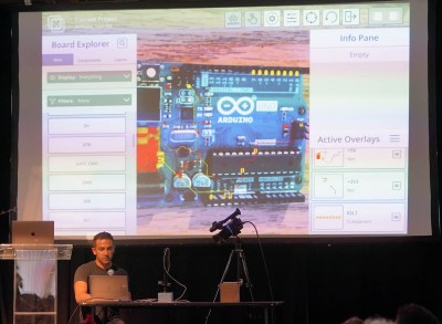
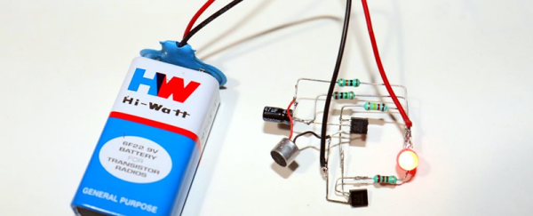
The transistor computer uses over 2000 individual transistors to implement everything comprising the 11-bit CPU. The creator, Reddit user [ Weekly_Salamander_78] also has an online interactive book that walks through each of the steps that is required to get to the point of having a working computer like this. Starting with a guide on building logic gates from transistors it will eventually cover the arithmetic logic unit, adders, memory, clocks, and everything else that is needed for the complete CPU to get up and running. The design does rely on an Arduino for memory to simplify some things, and in the end it’s able to run a Hello, World! program and play a simple dinosaur game as well.

Building a computer out of discrete components like this is an impressive accomplishment, although we might not envy the creator of it when it comes time for troubleshooting or maintenance of all of those individual components. Presumably it would be much easier to work on than something like a relay computer, but for now we’ll all take a moment to be thankful that almost no one needs to work on debugging vacuum tube computers anymore.

An RP2040 Powered Pick And Place

Pick and place machines are a wonder to behold, as they delicately and accurately place part after part. Unfortunately, they have to have a similarly wondrous price tag. Luckily, they aren’t too difficult to make yourself as they share many properties of a 3D printer with some extra constraints. [Stargirl Flowers] released Starfish, an open-source pick-and-place control board based around an RP2040 to help people make their own.

She purchased a LumenPnP, and the itch to tinker became too much to ignore. The STM32 on the stock controller also happened to get fried, leaving an obvious opening to create a custom board. [Stargirl] chose Trinamic TMC2209 motor controllers to drive the three stepper motors. The power circuit is impressively overbuilt with a 3A fuse, a TVS diode for shunting voltage spikes, a P-channel MOSFET for reverse polarity protection, a low-pass filter for AC ripple, and a large 100μF capacitor.

The RP2040 is a good choice since it’s easy to get and has plenty of digital I/O. USB connects the board to the outside work and includes ESD TVS diodes to protect the board when connecting and disconnecting the USB port. Motors for vacuums are controlled by a 74HC2G34 buffer that drives enable lines to two MOSFETs. Solenoids are similar but with a high current peak and a much smaller current to keep them open. The DRV120 fits the bill as it is a single-channel relay with current regulation. I2C vacuum sensors are the same ones on the Lumen motherboard; they just required an I2C multiplexer.

It’s an extremely well-documented project explaining why each part was chosen and why. If you want to create an RP2040 project that needs to last, we consider this a guiding star. It’s all up on GitHub for you to take a look at.

This isn’t the first time we’ve seen RP2040 as part of a motor controller, and we suspect we’ll see more.

Simple Stopwatch with two buttons, an eight digit 7-segment display and ICSP programming cable going into the board

Add An OSHW Certified Stopwatch To Your Toolkit

[MakingDevices] has created a simple stopwatch that makes for a nice introduction to surface mount electronic design and assembly. The project is open source hardware (OSHW) certified, with Gerbers, KiCAD files, and software all available.

Conceptually the stopwatch is straight forward, with a row of two four digit seven-segment displays being driven by a PIC18LF14k50 microcontroller through multiple NPN transistors. The PIC doesn’t quite have enough data lines to drive the two displays at once so an inverter is used to toggle between the two seven-segment blocks.

The circuit is continuously powered from a CR2032 coin cell battery. For normal usage with display, [MakingDevices] estimates 30+ hours of operation and 140+ hours without display, but still counting time. When idle, the “Extreme Low-Power (XLP)” capabilities of the PIC put the operating window estimates well beyond the self discharge of the coin cell battery. There’s an in circuit serial programming (ICSP) footprint that accepts a pogo pin TC2030-MCP-NL adapter for flashing the PIC.

Don’t let the simplicity fool you, this is a well documented project with detailed posts about the design, simulation and battery consumption. Various videos and glamour shots give a whole picture of the process, from design, assembly, testing to final validation.

It’d be wonderful to see the project extended or hacked on further, perhaps with a cute enclosure or case.

Continue reading “Add An OSHW Certified Stopwatch To Your Toolkit”

Liberating The ESP8266 From Its Development Board

While the ESP32 is clearly a superior piece of hardware, we think you’ll agree that the ESP8266 is just too useful not to have a dozen or so kicking around the parts bin at any given time. Cheap, easy to use, and just enough capabilities to bring your projects into the wonderful world of IoT. But if you really want to get the most out of it, you’ll eventually have to skip the development board and start working with the bare module itself.

It can be a scary transition, but luckily, [Ray] has collected some notes that should prove helpful for anyone looking use modules like the ESP-12F in their own custom PCBs. From different tips on making sure the power-hungry modules get enough juice, to cost cutting measures that help reduce the ancillary parts needed in your circuit design, it’s a worthwhile read for new and experienced ESP8266 wranglers alike.

An auto-reset circuit with the CH340C

For example, [Ray] talks a bit about using the infamous GPIO10 pin. This pin is on the rear of the ESP8266 module, and on many development boards, it isn’t even connected. That’s because its internally hooked up to the ESP8266’s SPI flash chip, and using it can cause problems if you’re not careful. But as explained in the blog post, as long as you make sure the flash mode is set to “dual IO” (DIO), then GPIO10 can be used just like any other free pin.

We also really liked the tip [Ray] shares at the end for making your boards more easily programmable. Sure you can leave an unpopulated header on the board, or fiddle with some pogo pin setup, but his edge connector approach is quite clever. Just slip the programmer on for the initial burn, and then after that you can update over the air.

There’s no denying how easy it is to throw something together with an ESP8266 development board, but we’ve covered so many incredible projects that have made use of the bare module’s diminutive dimensions that you’ll ultimately be missing out if you don’t cut out the middle-man.

Investigating A New Chip In A Minimalist LED Lamp

Teardowns of cheap electronic devices can produce results that are interesting, horrifying, or both, especially when mains power is involved. [bigclivedotcom] gave a minimalist LED lamp his reverse engineering treatment, and discovered a new chip that requires only four additional passive components to run LEDs on AC power.

The chip in question is a Joulewatt JWB1981, for which no datasheet is available on the internet. However, there is a datasheet for the JW1981, which is a linear LED driver. After reverse-engineering the PCB, [bigclivedotcom] concluded that the JWB1981 must include an onboard bridge rectifier. The only other components on the board are three resistors, a capacitor, and LEDs. The first resistor limits the inrush current to the large smoothing capacitor. The second resistor is to discharge the capacitor, while the final resistor sets the current output of the regulator. 

It is possible to eliminate the smoothing capacitor and discharge resistor, as other LED circuits have done, which also allow the light to be dimmable. However, this results in a very annoying flicker of the LEDs at the AC frequency, especially at low brightness settings.

As always, this is a very informative video from [bigclivedotcom], and it was all done based on a single picture of the PCB sent in by a viewer. He also mentions that the lifespan of the lamp would likely be increased by swapping out the current setting resistor for a larger one.

We’ve covered several [bigclivedotcom]’s videos, covering topics from self-powered wireless switches to filling up fake capacitors with electrolyte.

Continue reading “Investigating A New Chip In A Minimalist LED Lamp”

Debugging PCBs With Augmented Reality

Mihir Shah has designed many a PCB in his time. However, when working through the development process, he grew tired of the messy, antiquated methods of communicating design data with his team. Annotating photos is slow and cumbersome, while sending board design files requires everyone to use the same software and be up to speed. Mihir thinks he has a much better solution by the name of InspectAR, it’s an augmented reality platform that lets you see inside the circuit board and beyond which he demoed during the 2019 Hackaday Superconference.

The InspectAR package makes it easy to visualise signals on the board.

The idea of InspectAR is to use augmented reality to help work with and debug electronics. It’s a powerful suite of tools that enable the live overlay of graphics on a video feed of a circuit board, enabling the user to quickly and effectively trace signals, identify components, and get an idea of what’s what. Usable with a smartphone or a webcam, the aim is to improve collaboration and communication between engineers by giving everyone a tool that can easily show them what’s going on, without requiring everyone involved to run a fully-fledged and expensive electronics design package.

The Supercon talk served to demonstrate some of the capabilities of InspectAR with an Arduino Uno. With a few clicks, different pins and signals can be highlighted on the board as Mihir twirls it between his fingers. Using ground as an example, Mihir first highlights the entire signal. This looks a little messy, with the large ground plane making it difficult to see exactly what’s going on. Using an example of needing a point to attach to for an oscilloscope probe, [Mihir] instead switches to pad-only mode, clearly revealing places where the user can find the signal on bare pads on the PCB. This kind of attention to detail shows the strong usability ethos behind the development of InspectAR, and we can already imagine finding it invaluable when working with unfamiliar boards. There’s also the possibility to highlight different components and display metadata — which should make finding assembly errors a cinch. It could also be useful for quickly bringing up datasheets on relevant chips where necessary.

Obviously, the electronic design space is a fragmented one, with plenty of competing software in the market. Whether you’re an Eagle diehard, Altium fanatic, or a KiCad fan, it’s possible to get things working with InspectAR. Mihir and the team are currently operating out of office space courtesy of Autodesk, who saw the value in the project and have supported its early steps. The software is available free for users to try, with several popular boards available to test. As a party piece for Supercon, our very own Hackaday badge is available if you’d like to give it a spin, along with several Arduino boards, too. We can’t wait to see what comes next, and fully expect to end up using InspectAR ourselves when hacking away at a fresh run of boards!

DIY Clapper Lets You Pick Your Components

One thing that always means the end of the year is close is the reappearance of TV ads for “The Clapper.” After all, who needs home automation when you can clap on and clap off? While we’re partial to our usual home automation solutions, [Utsource123] shows us that building a clapper can be a fun and easy project using several similar circuits. One with a few transistors and another one with a 555 because, after all, what can’t a 555 do?

Of course, these circuits usually have a microphone. We were trying to think of how you could make a sound-sensitive element out of common parts. After all, you don’t care about the fidelity of the microphone pickup, just that it hears a loud noise. The circuits are about what you’d expect. The transistor version uses one to amplify the microphone and another to switch on the LED. You’d need a bit more to trigger a relay. The 555 uses an even simpler preamp transistor as a trigger.

While we aren’t bowled over with the idea of a clapper, we imagine these circuits aren’t far removed from the ones you buy in stores. For about $16 you also get enough switching to handle a simple AC load, though. Maybe Alexa and Google should allow making clapping a wake up word?

This is sure simpler than the last clapper clone we saw. Then there’s the deluxe DIY version.