Exploring Woodworking Mysteries With Strain Gauges And Raspberry Pi

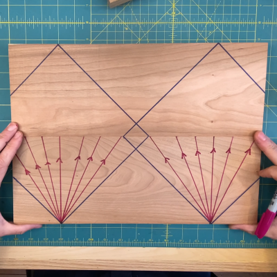
If you’re not a woodworker, you might not have heard of the “45-degree rule.” It goes like this: a clamp exerts a force that radiates out across a triangular region of the wood that forms a right angle — 45 degrees on each side of the clamp’s point of contact. So, to ensure that force is applied as evenly as possible across the entire glue joint, clamps should be spaced so that these force triangles overlap. It’s a handy rule, especially for the woodworker looking to justify the purchase of more clamps; you can never have too many clamps. But is it valid?
Myth busted?

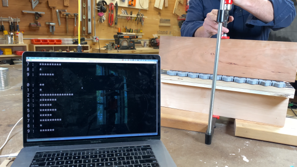
The short answer that [ari kardasis] comes up with in the video below is… sort of. With the help of a wonderfully complex array of strain gauges and a Raspberry Pi, he found that the story isn’t so simple. Each strain gauge lives in a 3D printed bracket that spaces the sensors evenly along the wood under test, with a lot of work going into making the test setup as stiff as possible with steel reinforcement. There were some problems with a few strain gauges, but once he sorted that out, the test setup went into action.

[ari] tested clamping force transmission through pieces of wood of various widths, using both hardwoods and softwoods. In general, he found that the force pattern is much broader than the 45-degree rule suggests — he got over 60 degrees in some cases. Softwoods seemed to have a somewhat more acute pattern than hardwoods, but still greater than the rulebook says. At the end of the day, it seems like clamp spacing of two board widths will suffice for hardwoods, while 1.5 or so will do for softwoods. Either way, that means fewer clamps are needed.

A lot of woodworking is seat-of-the-pants stuff, so it’s nice to see a more rigorous analysis like this. It reminds us a lot of some of the experiments [Matthia Wandel] has done, like load testing various types of woods and glues.

Continue reading “Exploring Woodworking Mysteries With Strain Gauges And Raspberry Pi”

A Trip Down The Vacuum Clamping Rabbit Hole

We all know how easy it is to fall down the rabbit hole,  something that turns a seemingly simple job into an accidental journey of experimentation and discovery. And perhaps nobody is more prone to rabbit-holing than [Matthias Wandel], at least judging by his recent foray into quantitating different techniques for vacuum clamping in the woodshop. (Video, embedded below.)

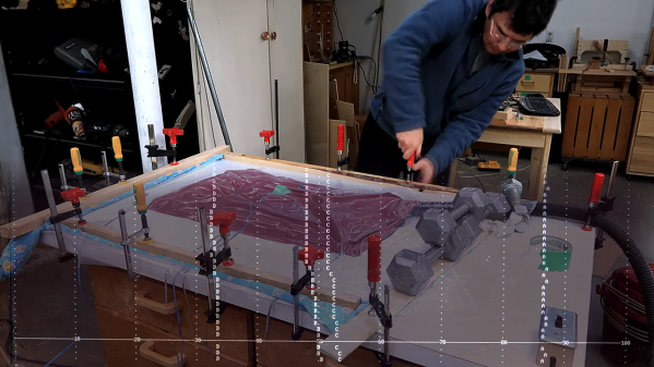
To understand where this all came from, you’ll have to dial back to [Matthias]’s first video, where he was just trying to make a simple corkboard. In an effort to get even pressure over the whole surface of the board, he came up with a shop-expedient vacuum clamp, made from a sheet of thick plastic, some scraps of wood and clamps, and a couple of vacuums. With the workpiece sandwiched between a smooth, flat table and the plastic sheet, he was able to suck the air out and apply a tremendous amount of force to the corkboard.

The comments to the first video led to the one linked below, wherein [Matthias] aimed to explore some of the criticisms of his approach. Using a quartet of BMP280 pressure sensor breakout boards and a Raspberry Pi, he was able to nicely chart the pressure inside his clamping jig. He found that not only did the sensors make it easy to find and fix leaks, they also proved that adding a porous layer between the workpiece and the vacuum bag wouldn’t likely improve clamping. He was also able to show which of his collection of vacuums worked best — unsurprisingly, the Miele sucked the hardest, although he found that it wasn’t suitable for continuous clamping duty.

We can see a lot of uses for a jig like this, and we really like it when trips down the rabbit hole yield such interesting results. Especially quantitative results; remember [Matthias]’s exploration of basement humidity?

Continue reading “A Trip Down The Vacuum Clamping Rabbit Hole”

What Does ESD Do To My Circuit And How Can I Protect Against It?

[Kevin Darrah] is risking the nerves on his index finger to learn about ESD protection. Armed with a white pair of socks, a microfiber couch, and a nylon carpet, like a wizard from a book he summons electricity from his very hands (after a shuffle around the house). His energy focused on a sacrificial 2N7000 small signal MOSFET.

So what happens to a circuit when you shock it? Does it instantly die in a dramatic movie fashion: smoke billowing towards the roof, sirens in the distance? [Kevin] set up a simple circuit to show the truth. It’s got a button, a MOSFET, an LED, and some vitamins. When you press the button the light turns off.

He shuffles a bit, and with a mini thunderclap, electrocutes the MOSFET. After the discharge the MOSFET doesn’t turn the light off all the way. A shocking development.

So how does one protect against these dark energies out to destroy a circuit. Energies that can seemingly be summoned by anyone with a Walmart gift card? How does someone clamp down on this evil?

[Kevin] shows us how two diodes and a resistor can be used to shunt the high voltage from the electrostatic discharge away from the sensitive components. He also experimentally verifies and elucidates on the purpose of each. The resistor does nothing by itself, it’s there to protect the diodes. The diodes are there to protect the MOSFET.

In the end he had a circuit that could withstand the most vigorous shuffling, cotton socks against nylon carpeting, across his floor. It could withstand the mighty electric charge that only a grown man jumping on his couch can summon. Powerful magics indeed. Video after the break.

Continue reading “What Does ESD Do To My Circuit And How Can I Protect Against It?”