If you didn’t know better, you might think the phrase “class A amplifier” was a marketing term to help sell amplifiers. But it is, of course, actually a technical description of an amplifier that doesn’t distort the input waveform because it doesn’t depend on multiple elements to handle different areas of the input waveform. Want to know more? [FesZ] has a new video covering the basics of class A amplifiers including some great simulations. You can see the video below.
A class A amplifier uses a transistor that is always biased on. It never saturates or switches off. This is good for linearity, but not always the best for efficiency so there are other classes of amplifiers, too. However, for many applications, class A is the most common configuration.
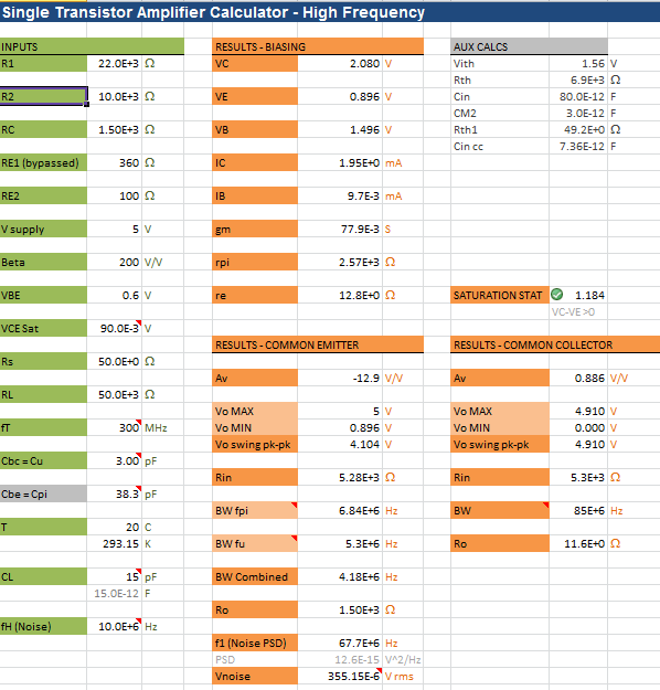
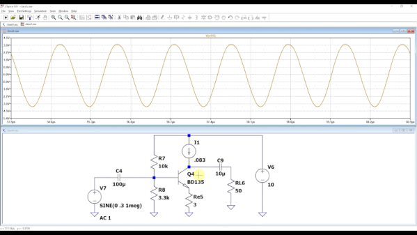
There are a number of trade-offs involved with each type of amplifier and [FesZ] covers them in detail. But the real interesting part is the simulations in Spice. Sure, you can build the circuits and look at everything with a meter or scope, but using Spice is much handier.
There is a second video upcoming. We hope he covers other amplifier types too, as you really do want to understand the differences when you need to design something. If you want more Spice stuff, check out some of our previous posts. If for some reason, you don’t like LTSpice, there’s always Micro-Cap 12.