A 3D Printer To PCB Miller Conversion

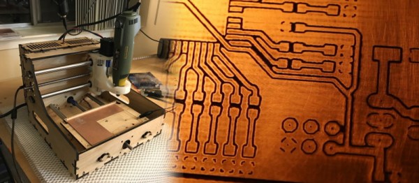
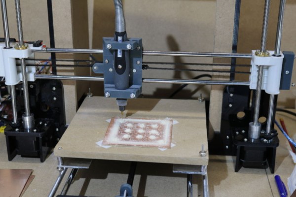
Got a 3D printer? With a bit of work, you may also have a PCB miller. That’s the basis of this neat hack by [Gosse Adema], who converted an Anet A8 3D printer into a PCB miller by building a holder for a Dremel rotary tool and adapting the GCode. This approach means that the adaptations to the printer are minimal: the only hardware is a 3D-printed holder for the Dremel that replaces the print head. The result is an impressive PCB milling machine that can do double-sided PCBs and make through holes.

The excellent write-up that [Gosse] did on this hack describes how he converted the printer, and how he took an EagleCAD design and converted it into four GCode files. That’s one for each side of the PCB, one for through holes and one for the final outline of the PCB. These are then fed to the 3D printer and cut in turn with an appropriate milling bit on the Dremel.

We’ve featured a few similar conversions before, such as this vintage conversion of a Makerbot and this cheap engraver conversion, but this one is much more detailed than those, covering the entire process from PCB design to final product.

Soundproofing A CNC Mill Conversion

The Proxxon MF70 is a nice desktop sized milling machine with a lot of useful add-on accessories available for it, making it very desirable for a hacker to have one in his or her home workshop. But its 20000 rpm spindle can cause quite the racket and invite red-faced neighbors. Also, how do you use a milling machine in your home-workshop without covering the whole area in metal chips and sawdust? To solve these issues, [Tim Lebacq] is working on Soundproofing his CNC mill conversion.

To meet his soundproof goal, he obviously had to first convert the manual MF70 to a CNC version. This is fairly straightforward and has been done on this, and similar machines, in many different ways over the years. [Tim] stuck with using the tried-and-tested controller solution consisting of a Raspberry Pi, an Arduino Uno and a grbl shield sandwich, with stepper motor drivers for the three NEMA17 motors. The electronics are housed inside the reclaimed metal box of an old power supply. Since the Proxxon MF70 is already designed to accept a CNC conversion package, mounting the motors and limit switches is pretty straightforward making it easy for [Tim] to make the upgrade.

Soundproofing the box is where he faced unknown territory. The box itself is made from wooden frames lined with particle board. A pair of drawer slides with bolt-action locks is used for the front door which opens vertically up. He’s also thrown in some RGB strips controlled via the Raspberry-Pi for ambient lighting and status indications. But making it soundproof had him experimenting with various materials and techniques. Eventually, he settled on a lining of foam sheets topped up with a layer of — “bubble wrap” ! It seems the uneven surface of the bubble wrap is quite effective in reducing sound – at least to his ears. Time, and neighbours, will tell.

Maybe high density “acoustic foam” sheets would be more effective (the ones similar to “egg crate” style foam sheets, only more dense)? Cleaning the inside of the box could be a big challenge when using such acoustic foam, though. What would be your choice of material for building such a sound proof box? Let us know in the comments below. Going back many years, we’ve posted about this “Portable CNC Mill” and a “Mill to CNC Conversion” for the Proxxon MF70. Seems like a popular machine among hackers.

Home Made 5-Axis CNC Head Is A Project To Watch

[Reiner Schmidt] was tired of renting an expensive 5-axis CNC head for projects, so he decided to build his own. It’s still a work in progress, but he’s made remarkable progress so far. The project is called Bridge Boy, and it is designed to use a cheap DC rotary mill to cut soft materials like plastic, wood and the like. Most of it is 3D printed, and he has released the Autodesk 360 plans that would allow you to start building your own. His initial version uses an Arduino with stepper drivers, and is designed to fit onto the end of a 60mm arm of a standard 3-axis CNC,  so technically it’s a 3+2 axis CNC. With the appropriate software, it should be able to work as a full 5-axis machine, though, and it should be possible to integrate it with a CNC that has a 5-axis driver board without too much effort.

Continue reading “Home Made 5-Axis CNC Head Is A Project To Watch”

Hackaday Prize Entry: CNC Mill Lets Kids Engrave On The Fly

The manufacturing revolution has already begun, and there are 3D printers, CNC machines, and laser cutters popping up in garages and workspaces all around the world. The trouble with these machines is that they’re fiddly to use, and you don’t want a kid playing around with them.

[moritz.messerschmidt]’s Hackaday Prize entry is a desktop Badgemaker that engraves acrylic name badges for kids. Under the hood, an Arduino with a custom-built shield with 3 SilentStepStick stepper drivers on it operates the three NEMA-11 motors. Meanwhile, the kids interact with a 7” touchscreen powered by a Raspberry Pi.

Once the kid selects what to engrave, motors move the piece of acrylic against a rotary tool’s milling bit, carving the acrylic as instructed. These cards are then equipped with watch batteries and LEDs to light up.

The touch screen is key. Bummed out by basic CNC machines that were difficult to use — like hobbyist 3D printers with a newbie-befuddling interface — [moritz.messerschmidt] went out of his way to make the interface kid-friendly, with just a simple set of choices necessary for creating one’s own name badge.

Is this a feature-packed CNC machine with all the bells and whistles? No, but that’s not the point. The purpose of the Badgemaker is to introduce a new generation to personal fabrication technology. It’s a toy, but that’s the point: a CNC machine that’s so easy to use, even a child can do it.

CNC Mill Out Of A Building Set

I have some aluminum building-set parts on hand and just got a second rotary tool, so I thought I’d try my hand at making a light-duty CNC mill—maybe carve up some cheap pine or make circuit boards. This post explores some of the early decisions I’m facing as I begin the project.

Of primary importance is the basic format of the mill’s chassis. Gantry configuration or put everything in a box of girders? How will the axes move–belts or racks? How will the Z-axis work, the assembly that lowers the tool onto the material? Finally, once the chassis is complete, or perhaps beforehand, I’ll need to figure out how I intend to control the thing.

Continue reading “CNC Mill Out Of A Building Set”

Home Built PCB Mill Reportedly Doesn’t Suck

It’s 2017, and getting a PCB professionally made is cheaper and easier than ever. However, unless you’re lucky enough to be in Shenzhen, you might find it difficult to get them quickly, due to the vagaries of international shipping. Whether you want to iterate quickly on designs, or just have the convenience of speed, it can be useful to be able to make your own PCBs at home. [Timo Birnschein] had just such a desire and set about building a PCB mill that doesn’t suck.

It might sound obvious, but it bears thinking about — if you know you’re incapable of building a good PCB mill in a reasonable period of time, you might save yourself a lot of pain and lost weekends by just ordering PCBs elsewhere. [Timo] was fairly confident however that the build would be able to churn out some usable boards, however, and got to work.

The build is meant to be accessible to the average hacker who wants one. The laser cut & 3D printed parts are readily available these days thanks to online services that can manufacture for those who don’t have the machines at home. [Timo] uses a rotary multitool for a spindle, a common choice for a budget CNC build.

With the hardware complete, [Timo] has spent time working on optimising the software side of things. Through careful optimisation of the G-Code, [Timo] has been able to improve performance and reduce stress on the tooling. It’s not enough to just build a good mill — you’ve got to have your G-Code squared away as well.

Overall, the results speak for themselves. The boards don’t suck; the mill can do traces down to 8 mil, and even drill the holes. We’d love to have one on the workbench when busting out some quick prototypes. For another take on the home-built PCB mill, why not check out this snap-together version?

Zeroing CNC Mills With OpenCV

For [Jay] and [Ricardo]’s final project for [Dr. Bruce Land]’s ECE4760 course at Cornell, they tackled a problem that is the bane of all machinists. Their project finds the XY zero of a part in a CNC machine using computer vision, vastly reducing the time it take to set up a workpiece and giving us yet another reason to water down the phrase ‘Internet of Things’ by calling this the Internet of CNC Machines.

For the hardware, [Jay] and [Ricardo] used a PIC32 to interface with an Arducam module, a WiFi module, and an inductive sensor for measuring the distance to the workpiece. All of this was brought together on a PCB specifically designed to be single-sided (smart!), and tucked away in an enclosure that can be easily attached to the spindle of a CNC mill. This contraption looks down on a workpiece and uses OpenCV to find the center of a hole in a fixture. When the center is found, the mill is zeroed on its XY axis.

The software is a bit simpler than a device that has OpenCV processing running on a microcontroller. Detecting the center of the bore, for instance, happens on a laptop running a few Python scripts. The mill attachment communicates with the laptop over WiFi, and sends a few images of the downward-facing camera over to the laptop. From there, the laptop detects the center of the bore in the fixture plate and generates some G-code to send over to the mill.

While the device works remarkably well, and is able to center the mill fairly quickly and without a lot of user intervention, there were a few problems. The camera is not perfectly aligned with the axis of the spindle, making the math harder than it should be. Also, the enclosure isn’t rated for being an environment where coolant is sprayed everywhere. Those are small quibbles, and these problems could be fixed simply by designing and printing another enclosure. The device works, though, and really cuts down on the time it takes to zero out a mill.

You can check out the video description of the build below.

Continue reading “Zeroing CNC Mills With OpenCV”