Easy Rotary Encoding For Your Projects

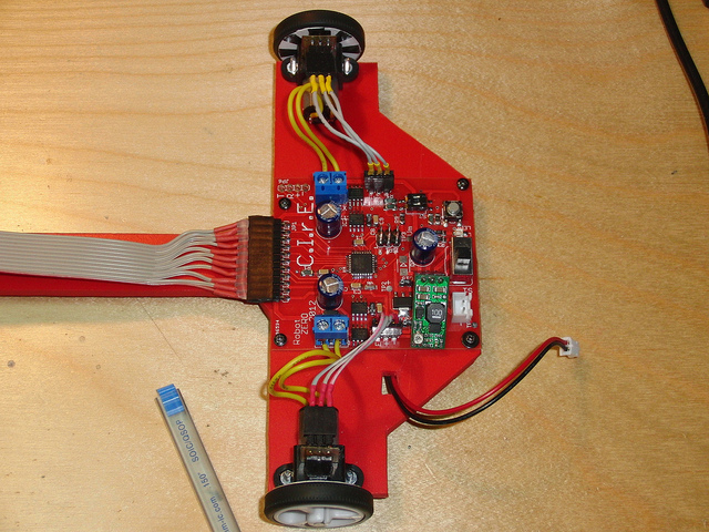
Want to monitor how much a wheel has turned in your project? Then you need a rotary encoder! Here’s a way to add rotary encoding without changing the mounting method of your wheels (translated). [Jorge] added it as a way to improve the functionality of this line-following robot. It uses a paper encoder wheel which is monitored by an optical sensor.

The paper wheel consists of alternating white and black pie pieces. You can make this with a felt-tipped marker, or use a tool like the one we featured a couple of years ago to print out a disc rendered to your own specifications. This is glued to the inside of the wheel and monitored by a CNY70 reflective sensor (the same one used in that electric keyboard retrofit).

The homemade board which holds the sensor can be seen mounted on top of each wheel’s motor. It requires three wires, voltage, ground, and data. The data line is connected to the output of the phototransistor in the CNY70 package so it can be used with a microcontroller interrupt for easy integration with the firmware driving the robot.

[Jorge] goes into some detail about how the added data helps to improve the speed performance seen in the clip after the break.

Continue reading “Easy Rotary Encoding For Your Projects”

Playing Piano With Optical Sensors

[Sebastian] is trying to improve the responsiveness of an electric keyboard. He was unsatisfied with the lack of adequate sensitivity to keystroke. The first step in his process was to measure how fast the quickest keystroke actually is. By setting up an LED and phototransistor and taking some measurements he found that sampling at 1 kHz would be more than adequate.

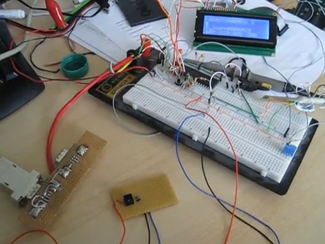
With initial testing complete he ordered some CNY70 transmissive/reflective light sensors that can be place below the keys. He measures the sensor with the ADC on an ATmega16 microcontroller. Running at 16 MHz he can sample each of the eight analog-to-digital converter channels at 1202 Hz. After doing a bunch of math he put together some lookup tables that are used to translate the ADC data into midi signals. We’ve embedded a video of one sensor controlling the midi program PianoTeq. [Sebastian] also sent us a schematic of one node in the sensor network (see it after the break).

When everything is said and done he plans to use eleven ATmega16 microcontrollers to address the 88 keys, with an additional microcontroller to act as the master using a two-wire interface for communications.

Update: [Sebastian] put up a webpage with a fairly verbose description. Reading it straight from the source really clears up a lot of questions.


Continue reading “Playing Piano With Optical Sensors”