Here’s a really fascinating circuit that implements a combination lock using relays and logic gates. Even with the schematic and written explanation of how it works we’re still left somewhat in the dark. We’ll either pull out some paper and do it by hand this weekend, or build it chunk by chunk in a simulator like Atanua. Either way, the project sparked our interest enough that we want to get elbow deep into its inner workings.
From the description we know that it uses a combination of CD4017, CD4030, CD4072, and CD4081 chips. You’re probably familiar with the 4017 which is a decade counter popular in a lot of project. The other chips provide XOR, OR, and AND gates respectively. The relays were chosen for two purposes. One of them activates when a correct combination has been entered, effectively serving as the output for the combo lock. The other two are for activating the clock and affecting a reset if the wrong combination is entered.
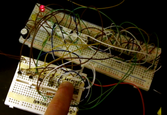
It makes us wonder if this would be incredibly simple to brute force the combination by listening for sound of the reset relay activating? It’s hard to tell from the video after the break if you can discern a wrong digit from a right once just based on sound.


