Linear Power Supply’s Current Limiter Is A Lesson In Simplicity

Here at Hackaday we really like to feature projects that push the limits of what’s possible, or ones that feature some new and exciting technology that nobody has ever seen before. So what’s so exciting about this single-voltage linear power supply? Honestly, nothing — until you start looking at its thermally compensated current limiting circuit.

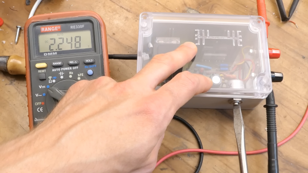
This one is by [DiodeGoneWild], who you’ve really got to hand it to in terms of both the empirical effort he went through to optimize the circuit, as well as the quality of his explanation. The basic circuit is dead simple: a transformer, a full-wave rectifier, an LD1085 adjustable regulator — a low-dropout version of the venerable LM317 — and associated filter caps and trimmer pot to adjust the output between 2.2 and 5.5 volts.

The current limiting circuit, though, is where things get interesting. Rather than use an op-amp, [DiodeGoneWild] chose a simple discrete transistor current-sense circuit. To make it less susceptible to thermal drift, he experimented with multiple configurations of resistors and Schottky diodes over a wide range of temperatures, from deep-freeze cold to hair-dryer-in-a-box hot. His data table and the resulting graph of current versus temperature are works of art, and they allowed him to make sensible component selections for a fixed 250-mA current limit with a reasonably flat thermal response.

As for construction, it’s all classic [DiodeGoneWild], including a PCB with traces ground out with a Dremel and a recycled heat sink. He also dropped a couple of interesting build techniques, like adding leads to turn SMD tantalum caps into through-hole components. The video below shows all the build details along with the exhaustive breadboard testing.

From taking on a potentially risky magnetron teardown to harvesting lasers from headlights, there’s always something to learn from a [DiodeGoneWild] video.

Continue reading “Linear Power Supply’s Current Limiter Is A Lesson In Simplicity”

DrLCD Is Here To Give Your MSLA Printer A Checkup

Over the last couple years, we’ve seen an absolute explosion of masked stereolithography (MSLA) 3D printers that use an LCD screen to selectively block UV light coming from a powerful LED array. Combined with a stepper motor that gradually lifts the build plate away from the screen, this arrangement can be used to produce high-resolution 3D prints out of photosensitive resins. The machines are cheap, relatively simple, and the end results can be phenomenal.

But they aren’t foolproof. As [Jan Mrázek] explains, these printers are only as good as their optical setup — if they don’t have a consistent UV light source, or the masking LCD isn’t working properly, the final printed part will suffer. In an effort to better understand how these factors impact print quality, he designed the DrLCD: a TSL2561 luminosity sensor mounted to a robotic arm with associated software to map out the printer’s light source.

The individual LED assemblies are clearly visible.

The results when running DrLCD against a few different types of printers is fascinating. [Jan] was clearly able to make out the type of lenses used, and in one case, was even able to detect that a darker spot in the scan was due to a bit of resin having leaked into the light source and clouded up the optics.

But DrLCD can do more than just tell you where you’ve got a dark spot. Using the data collected from the scan, it’s possible to create a “compensation map” that can be combined with the sliced model you wish to print. As the slicer assumes an idealistic light source, this map can help by adding additional masking where bright spots in the display have been detected.

[Jan] goes on to compare the dimensional accuracy of printed parts before and after the compensation map has been applied to the model, and was able to identify a small but distinctive improvement. Not everyone is going to be concerned about the 157 µm deviation observed without the backlight compensation, but we certainly aren’t going to complain about 3D printers getting even more dimensionally accurate.

A couple years back we covered a similar technique that used a DSLR to capture high-resolution images of the bed. While arguably much easier to pull off, we can’t help but fall in love with the glorious overengineering that went into the DrLCD system, and we can’t wait until it starts making house calls.

Improving Exposure On A Masked SLA Printer

It’s taken longer than some might have thought, but we’re finally at the point where you can pick up an SLA 3D printer for a few hundred bucks. These machines, which use light to cure a resin, are capable of far higher resolution than their more common FDM counterparts, though they do bring along their own unique issues and annoyances. Especially on the lower end of the price spectrum.

[FlorianH] recently picked up the $380 SparkMaker FHD, and while he’s happy with the printer overall, he’s identified a rather annoying design flaw. It seems that the upgraded UV backlight in the FHD version of the SparkMaker produces somewhat irregular light, which in turn manifests itself as artifacts on the final print. Due to hot spots on the panel, large objects printed on the SparkMaker show fairly obvious scarring.

Now you might expect the fix for this problem to be in the hardware, but he’s taken it in a different direction. These printers use an LCD panel to block off areas of the UV backlight, thereby controlling how much of the resin is exposed. This is technique is officially known as “masked SLA”, and is the technology used in most of these new entry level resin printers.

As luck would have it, the SparkMaker FHD allows showing various levels of grayscale on the LCD rather than a simple binary value for each pixel. At least in theory, this allows [FlorianH] to compensate for the irregular backlight by adjusting how much the UV is attenuated by the LCD panel. He’s focusing on the printer he personally owns, but the idea should work on any masked SLA printer that accepts grayscale values.

The first step was to map the backlight, which [FlorianH] did by soaking thin pieces of paper in a UV reactant chemical, and draping them over the backlight. He then photographed the illumination pattern, and came up with some OpenCV code that takes this images and uses the light intensity data to compensate for the local UV brightness underneath the sliced model.

So far, this method has allowed [FlorianH] to noticeably reduce the scarring, but he thinks it’s still possible to do better. He’s released the code for this backlight compensation script, and welcomes anyone who might wish to take a look at see how it could be improved.

An uneven backlight is just one of the potential new headaches these low-cost “masked” SLA printers give you. While they’re certainly very compelling, you should understand what you’re getting into before you pull the trigger on one.

Automatic Daylight Saving Time Compensation For Your Clock Projects

Pretty early in development of my Ping Pong Clock I came up with the idea of automatic Daylight Saving Time compensation. It’s an interesting feature, but it’s a luxury and so I figured I could add it as a future improvement. Now’s the time and I’m reporting back on what I’ve learned and how you can add this to your own projects.

There’s two things to think about before adding this feature. Is it worth the effort and does it make the clock more confusing rather than easier to use?

As to the latter, if you are responsible for setting the time initially but you are not responsible for resetting the clock when we fall back or spring forward will it cause confusion? Perhaps initially, but the battery-backed RTC that I used in my project should mean that you set it once and never have to reset it again. The one exception is DST and that’s what I’m compensating for.

Whether it is worth it or not is difficult to answer until after the fact. You should take into consideration that the DST rules are not set in stone, they change from time to time. Add to that the fact that not all parts of the world observe the practice. This means that not only do you need to implement the compensation, but you should add a method of switching it on and off as well as changing the rules for when it is observed.

Join me after the break to learn the method and code I use to make time adjustments automatically twice a year.

Continue reading “Automatic Daylight Saving Time Compensation For Your Clock Projects”