An Arduino Programmable Load

Having a big block of hot to dump current into is a very useful thing to have if you’re testing batteries, power supplies, high power LEDs, electroplating, or any thing else that would normally require a huge resistor. [Jakub] found himself in need of an electronic load, and instead of a transistor and a pot, decided to make something more automatic: a programmable load built around an Arduino shield.

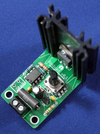
The idea behind this load is pretty simple: connect a device to a FET and shunt resistor to measure current. Drive the gate of the FET with an op-amp that maintains either constant current or constant voltage. Control everything with a DAC, and you have a programmable load controlled by an Arduino.

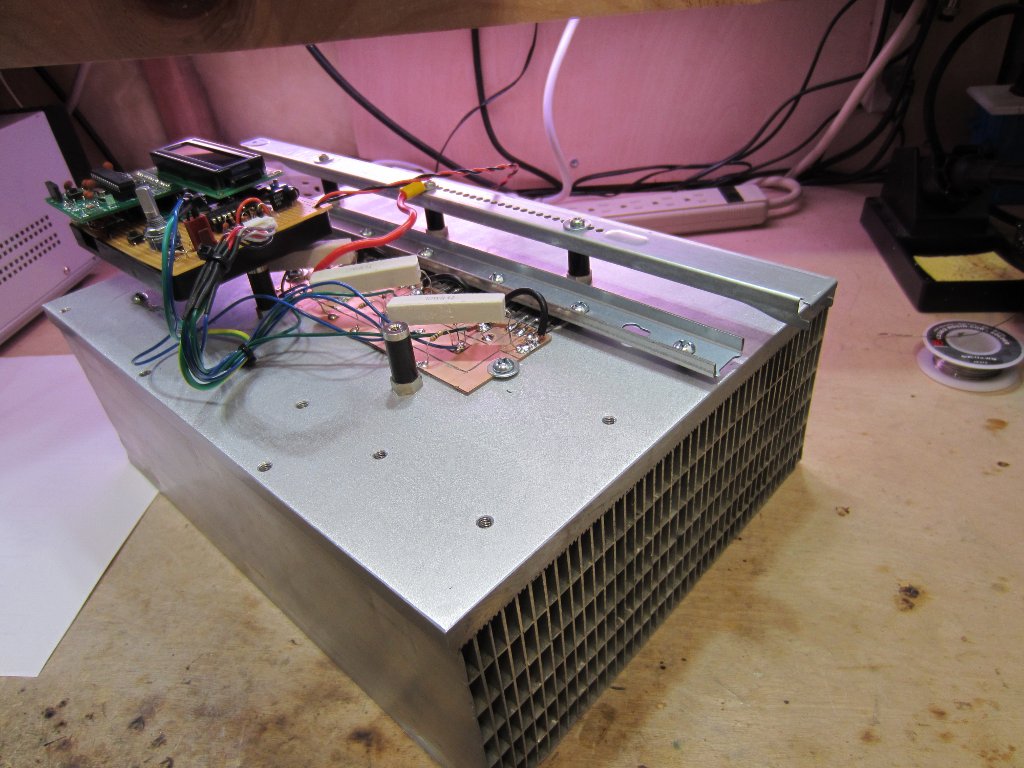
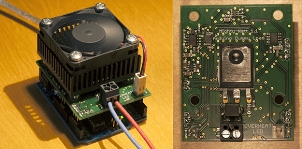
With such a small form factor, getting rid of all that heat was bound to be a problem. For this, [Jakub] is using a 50×50 mm BGA style heat sink with a 5V fan. If it’s good enough for a big CPU, it should be able to handle dumping 70 Watts into a FET. There’s also a conservative application of thermal paste and a very small thermistor underneath the FET that’s able to be read by the Arduino. It might slowly heat up your room, but it’s not going to catch fire.

With the Arduino sketches [Jakub] wrote for his load he was able to characterize a pair of Idea batteries and figure out how much charge a three-year-old recyclable battery had. It’s a great piece of work, and if [Jakub] is willing to go through the hassle of a Kickstarter, it would make a fine crowdfunded product.

Current Limiting Diode Use And Tutorial

Current limiting diode 1

Not that this happens often, but what do you do when faced with a repair where you don’t know the power source but you do know you have to drive LED backlighting? When faced with this dilemma [Eric Wasatonic’s] solution was to design for ambiguity. In this interesting hack repair [Eric] needed to restore backlighting for an old car stereo LCD display. First he guaranteed he was working with a DC power source by inserting a small full-wave bridge rectifier. Then knowing he needed 4 mA to power each LED for backlighting he used some 1978 vintage current limiting diodes designed to pass 2mA each regardless of voltage source, within limits of course.

Sure this is a simple hack repair but worthy of being included in anyone’s bag of tricks. Like most hacks there is always knowledge to be gained. [Eric] shares a second video where he uses a curve tracer and some datasheets to understand how these old parts actually tick. These old 1N5305 current limiting diode regulators are simply constructed from a JFET with an internal feedback resistor to its gate which maintains a fixed current output. To demonstrate the simplicity of such a component, [Eric] constructs a current limiting circuit using a JFET and feedback potentiometer then confirms the functionality on a curve tracer. His fabricated simulation circuit worked perfectly.

There was a little money to be made with this repair which is always an added bonus, and the recipient never reported back with any problems so the fix is assumed successful. You can watch the two videos linked after the break, plus it would be interesting to hear your thoughts on what could have been done differently given the same circumstances.

Continue reading “Current Limiting Diode Use And Tutorial”

Simple 10 Watt LED Driver Is Hot Stuff

[Peter] needed to drive a high power LED for his microscope. Rather than pick up a commercial LED driver, he built a simple constant current LED driver and fan control. We’ve featured [Peter’s] pumpkin candle LED work here on Hackaday in the past. Today he’s moving on to higher power LEDs. A 10 watt LED would be a good replacement light source for an old halogen/fiber optic ring light setup. [Peter] started with his old standby – an 8 pin Microchip PIC. In this case, a PIC12F1501. A PIC alone won’t handle a 10 watt LED, so he utilized a CAT4101 constant current LED driver from ON Semi. The PIC performs three tasks in this circuit. It handles user input from two buttons, generates a PWM signal to the LED driver, and generates a PWM signal for a cooling fan.

Control is simple: Press both buttons and the LED comes on full bright. Press the “up” button, and the LED can be stepped up from 10% to 100% in 10 steps.  The “down” button drops the LED power back down. [Peter] even had a spare pin. He’s currently using it as an LED on/off confirmation, though we’d probably use it with a 1wire temperature sensor as a backup to thermal protection built into the CAT4101. It may be overkill, but we’d also move the buttons away from that 7805 linear regulator. Being that this circuit will be used with a microscope, it may eventually be operated by touch alone. It would be a bit surprising to try to press a button and end up with a burnt fingertip!

Continue reading “Simple 10 Watt LED Driver Is Hot Stuff”

Building A DC Constant Current/Power Electric Load

By just looking at the picture above, we’re pretty sure that most Hackaday readers will have guessed by now that much power can be dissipated by this electric load. For those who don’t know, an electric load (or dummy load) is a device used to simulate a load on a system for testing purposes. This is quite handy when measuring battery capacities or testing power supplies.

The heart of the device that [Kerry] designed is based on 6 power MOSFETs, a few operational amplifiers and an Arduino compatible ATmega328p microcontroller. Sense resistors are used to measure how much current is passing through the MOSFETs (and therefore the load), the MCP4921 Digital to Analog Converter (DAC) from microchip is used to set the current command, and the load’s voltage is measured by the ATmega ADC. Measuring the latter allows a constant power load mode (as power = current * voltage). In his article, [Kerry] shows that he can simulate a load of up to 200W.

Continue reading “Building A DC Constant Current/Power Electric Load”

Shocking Your Brain And Making Yourself Smarter

tds

Transcranial Direct Current Stimulation – or tDCS – is the technique of applying electrodes to the skull and running a small but perceptible current through them. It’s not much current – usually on the order of 1 or 2 mA, but the effect of either increasing or decreasing neural activity has led to some interesting studies. [Theo] over on Instructables wrote a tutorial for making his own tDCS suppy that will supply 2 mA to electrodes placed on the skull for everyone to experiment with.

The basic idea behind tDCS is to put the positive electrode over the part of the brain to be excited or the negative electrode over the part of the brain to be inhibited. This is a well-studied technique that can be used to improve mathematical ability. It’s not electroshock therapy (although that is a valid treatment for depression and schizophrenia) in that a seizure is induced; tDCS just applies a small current to specific areas of the brain to excite or inhibit function.

[Theo]’s device is a simple circuit made of a transistor, resistors, and a few diodes to provide about 2 mA to a pair of electrical contacts. With this circuit and a few gel electrode pads for your head, you too can experiment with direct current stimulation of your brain.

Of course we need to warn you about putting electricity into your head. In any event, here’s a quadcopter / stun gun mashup we made. Don’t do that, either. You might get a takedown request.

Re:load, An Open Source Dummy Load

Re:load

When testing power supplies or LEDs, a constant current dummy load is needed. These devices will draw a constant amount of current, regardless of the voltage at the input terminals.

[Nick] was looking for a load to test out a power supply, and found commercial offerings to be too large, too powerful, and most importantly, too expensive. This lead to the design of the Re:load, his open source alternative.

Like other constant current sources, the Re:load uses an opamp to control a pass element. While most constant current loads will just use a transistor, [Nick] opted for a BTS117 smart low side switch IC. This device has a built in current limiter, over-voltage protection, over-temperature protection, and short circuit protection, which makes it much safer. The project write up goes into detail on how the device works.

If you need a constant current load, [Nick] is selling kits on Tindie. All the design files are available on Github so that you can build your own.

Color Changing Coaster Has A Built-in Drink Detector

[Robert] put together his own illuminated coasters that know when they hold a drink. They look fantastic, thanks to professionally produced PCBs and a layered, laser-cut acrylic case. They’re much like the pagers given to restaurant-goes who are waiting for tables, but this version is much fancier (and doesn’t include the vibrating/paging feature).

The RGB-LED board is a previous project which was developed using eight surface mount RGB LED modules around a circular board. It uses an ATmega168 paired with an MBI5168 constant-current LED sink driver. The coaster enclosure gave him room for a few more items, like the pair of AA batteries which work in conjunction with a boost converter to power the device. It also houses an IR reflectance sensor which is used to detect the presence of a drink on the coaster. This is important since an on-occupied coaster looks like it would be blindingly bright if there wasn’t a glass to diffuse the intensity of the LEDs.

He mentions that incandescent light bulbs mess with the IR reflectance sensor. But there must be some way to account for ambient conditions with the code, right?