A schematic for a continuity tester that modulates its pitch based on the resistance measured

Op Amp Contest: Clever Continuity Tester Tells You Where The Problem Is

A continuity tester, as found on most multimeters today, is a great tool for finding broken connections and short circuits. But once you’ve found a short, it’s up to you to figure out which part of the circuit it’s in – a tedious job on a large PCB with hundreds of components. [John Guy] aims to ease this task with a continuity tester that modulates the beeper’s tone according to the resistance measured in the circuit. Tracking down a short circuit is then simply a matter of probing multiple points along a track and observing whether the pitch goes up or down.

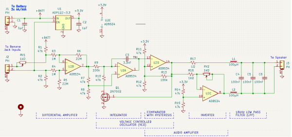
The circuit is based on a single AD8534 quad op amp chip. The first stage measures the voltage across the circuit under test in response to small current and amplifies it. The resulting signal is fed into a voltage-controlled oscillator (VCO) made from one op amp connected as an integrator and another working as a comparator with hysteresis. Op amp number four amplifies the resulting square wave and drives a speaker. A low-pass filter makes the sound a bit more pleasing to the ears by removing the higher notes.

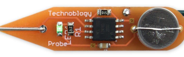
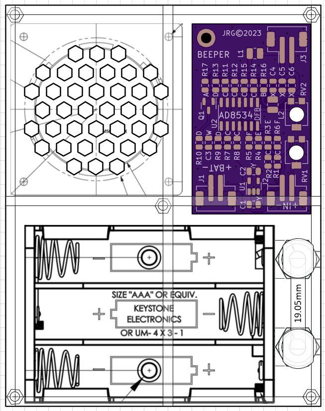
[John] paid particular attention to the PCB design to make it easy to assemble despite having a large number of SMD components on a small board. He even placed a parts list on the rear silkscreen, so anyone can assemble it even without the accompanying documents. The resulting board can be placed in a laser-cut acrylic case, turning it into a neat handheld instrument that will definitely find a place in any engineer’s toolbox. Measuring resistance through sound is not as accurate as using a full four-wire setup with an ohmmeter, but will be much faster and easier if you just want to find that annoying solder bridge hiding somewhere on your board.

Short Circuit Tracer For A Buck

Almost every meter you find today will have a continuity tester. Connect the probes and it will beep if there is a short and won’t if there isn’t. But where is the short? That’s another problem when trying to measure a component that is connected to many other components. [Learn Electronics Repair] wanted to have a tool to find shorts on a board and wanted to build a tester that uses 4-wire resistance measurement to isolate the device under test without having to do surgery on the circuit. His $1 build appears in the video below.

The first part of the video talks about the theory behind resistance measurement with two and four wires. Let shows several diagrams, but he mentions that at one point he shows an incorrect schematic (at 12:03) instead of the early correct one (at 10:35) and mentions it, but if you are skimming the video, you might get confused.

Continue reading “Short Circuit Tracer For A Buck”

Receiver board of the Ethernet tester, with only probing pins, and no resistors populated

Ethernet Tester Needs No LEDs, Only Your Multimeter

Ethernet cable testers are dime a dozen, but none of them are as elegant and multimeter-friendly as this tester from our Hackaday.io regular, [Bharbour]. An Ethernet cable has 8 wires, and the 9 volts of easily available batteries come awfully close to that – which is why the board has a voltage divider! On the ‘sender’ end, you just plug this board onto the connector, powered by a 9 volt battery. On the “receiver” end, you take your multimeter out and measure the testpoints – TP7 should be at seven volts, TP3 at three volts, and so on.

As a result, you can easily check any of the individual wires, as opposed to many testers which only test pair-by-pair. This also helps you detect crossover and miswired cables – while firmly keeping you in the realm of real-life pin numbers! This tester is well thought-out when it comes to being easily reproducible – the PCB files are available in the “Files” section, and since the “receiver” and “sender” PCBs are identical, you only need to do a single “three PCBs” order from OSHPark in order to build your own!

Bharbour has a rich library of projects, and we encourage you to check them out! If you ever want to get yourself up to speed on Ethernet basics, we’ve talked about its entire history – and we’ve even explained PoE! After some intensive learning time, perhaps you can try your hand at crimping the shortest Ethernet cable ever.

Build An Everlasting Continuity Tester

When you need a continuity tester at the bench, what do you reach for? Probably your multimeter, right? It may surprise you to know that the continuity tester in the meter isn’t all that sensitive, even if it’s the yellow expensive kind. [Leo]’s will beep even if there is 50Ω of resistance in the line.

Disgusted by modern commercial testers, [Leo] set out to make the ideal continuity tester in the spirit of old school tools that do one thing and do it really well. It had to be simple to use, always ready to go, and capable of measuring continuity at 5Ω or less resistance (video, embedded below).

There’s no power switch or even labels, because it doesn’t need any. Just put the probes where you want ’em, and it either beeps and lights the LED or it doesn’t. It looks simple, but inside that blast-resistant enclosure are lots of cool features that certainly make it seem like the ideal tester to us.

Our favorite has to be the transient blocking unit that works like a little circuit breaker. They’re used to protect circuits from lighting and electrostatic discharge by way of depletion-mode MOSFETs and switches to protected mode in under a microsecond. Watch [Leo] build this workbench necessity and then abuse test it with mains power after the break.

Making your own tools, however simple or complex is a great experience. If you want to up your speedy prototyping game, [Leo]’s got you covered there with a special scratching tool for hand-scribing copper PCBs. Continue reading “Build An Everlasting Continuity Tester”

This Vibrating Continuity Tester Is Quietly Useful

Continuity testing is one of the most valuable functions on the modern multimeter. It will help you investigate wiring problems in your car, tell you if you’re holding a nullmodem serial cable or the regular kind, and even reveal when you’ve accidentally shorted the data lines right to the power supply. However, all that beeping can get annoying, so [bitelxux] built a vibrating version instead.

The build was borne out of necessity; [bitelxux]’s meter lacked a buzzer, and it grew frustrating to always look at the display. In order to allow late night hacking sessions to go on undisturbed, an unobtrusive vibrating tester was desired, as opposed to the usual audible type. Two whiteboard markers donated their shells to the hack, fitted with small nails to act as probes. Inside, a pager vibration motor is connected, vibrating when continuity is found. The circuit runs from a 1.5V AA battery which neatly fits inside the marker shell.

It’s a basic build, but gets the job done with a minimum of fuss using parts that most makers probably have lying around. Of course, you can always go a slightly more complicated route and throw an Attiny at the problem.

Pocket-Sized Multiduino Does It All

How many times have you wished for a pocket-sized multimeter? How about a mini microcontroller-based testing rig? Have you ever dared to dream of a device that does both?

Multiduino turns an Arduino Nano into a Swiss Army knife of portable hacking. It can function as an analog multimeter to measure resistance, voltage drop, and continuity. It can also produce PWM signals, read from sensors, do basic calculator functions, and display the health of its rechargeable battery pack.

Stick a 10kΩ pot in the left-side header and you can play a space shooter game, or make line drawings by twisting the knob like an Etch-A-Sketch. Be sure to check out the detailed walk-through after the break, and a bonus video that shows off Multiduino’s newest functions including temperature sensing, a monophonic music player for sweet chiptunes, and a virtual keyboard for scrolling text on the OLED screen. [Danko] has a few of these for sale in his eBay store. They come assembled, and he ships worldwide. The code for every existing function is available on his site.

More of a maximalist? Then check out this Micro-ATX Arduino.

Continue reading “Pocket-Sized Multiduino Does It All”

Continuity Tester Uses The ATtiny85’s Comparator

There’s an inside joke among cyclists – the number of bikes you need is “n+1”, where “n” is your current number of bikes. The same probably also applies to the number of tools and equipment a hacker needs on their workbench. Enough is never enough. Although [David Johnson-Davies] has a couple of multimeters lying around, he still felt the urge to build a stand-alone continuity tester and has posted details for a super-simple ATtiny85 based Continuity Tester on his blog. For a device this simple, he set himself some tall design goals. Using the ATtiny85 and a few SMD discretes, he built a handy tester that met all of his requirements and then some.

The ATtiny85’s Analog Comparator function is perfectly suited for such a tester. One input of the comparator is biased such that there is a 51 ohm resistor between the input and ground. The output of the comparator toggles when the resistance between the other input and ground is either higher or lower than 51 ohms. Enabling internal pullup resistors in the ATtiny85 not only takes care of proper biasing of the comparator pins, but also helps reduce current consumption when the ATtiny85 is put to sleep. The test current is limited to 100 μA, making the tester suitable for use in sensitive electronics. And enabling the sleep function after 60 seconds of inactivity reduces standby current to just about 1 μA, so there is no need for a power switch. [David] reckons the CR927 button cell ought to last pretty long.

For those interested in building this handy tester, [David] has shared the Eagle CAD files as well as the ATtiny85 code on his Github repository or you could just order out some boards from OSHpark.