New Part Day: Modern PALs

Back in the bad old days, if you needed a little bit of custom logic you would whip out a tiny chip known as a PAL. A Programmable Logic Array is just what it sounds like and is the forerunner of modern, unsolderable CPLDs and FPGAs.

PALs and GALs have died off, left to the wastes of the Jameco warehouse, and now it seems the only programmable logic you can buy are huge, 100-pin monstrosities. [Nick] at Arachnid Labs was working on his Tsunami signal generator when a user asked if they could add just one more feature: a programmable divider to count 256 iterations of a clock. This is the perfect application for dumb logic, but if you’re looking for a part that’s not recommended for new designs, you only need to look to old programmable logic.

Enter the Greenpak. [Nick] had a dev kit for these ‘modern PALs’ sitting around and decided to give it a go. They’re small – they max out at 20 pins – but there are a few features that make it a little more interesting than a simple array of AND and OR gates. The Greenpak3 features analog comparators, look-up tables, RC oscillators, counters, and GPIO that will work well enough as circuit glue. They also work at 5V, something you’re just not going to find in more complex programmable logic.

These tiny chips are programmed in a graphical IDE, but the datasheet (PDF) includes full documentation for the bitstream; someone needs to write a Verilog or VHDL compiler for it soon. The one downside with these chips is that they’re tiny; 0.4mm pitch QFN packages. If you can solder that, you’re too good at soldering.

Hacklet 28 – Programmable Logic Hacks

FPGAs, CPLDs, PALs, and GALs, Oh My! This week’s Hacklet focuses on some of the best Programmable Logic projects on Hackaday.io! Programmable logic devices tend to have a steep learning curve.  Not only is a new hacker learning complex parts, but there are entire new languages to learn – like VHDL or Verilog. Taking the plunge and jumping in to programmable logic is well worth it though. High-speed projects which would be impossible with microcontrollers are suddenly within reach!

fpga-hdmi
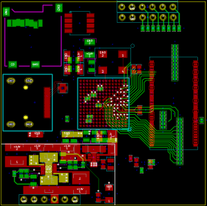
A great example of this is [Tom McLeod’s] Cheap FPGA-based HDMI Experimenting Board. [Tom’s] goal was to create a board which could output 720p video via HDMI at a reasonable frame rate. He’s using a Xilinx Spartan 6 chip to do it, along with a handful of support components. The images will be stored on an SD card. [Tom] is hoping to do some video with the setup as well, but he has yet to see if the chip will be fast enough to handle video decoding while generating the HDMI data stream. [Tom] has been quiet on this project for a few months – so we’re hoping that either he will see this post and send an update, or that someone will pick up his source files and continue the project!

ardufpga
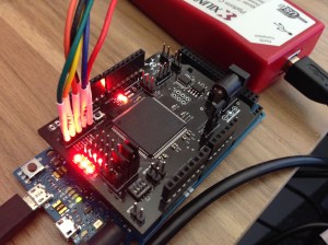
Next up is our own [technolomaniac] with his Arduino-Compatible FPGA Shield. Starting out with FPGAs can be difficult. [Technolomaniac] has made it a bit easier with this shield. Originally started as a project on .io and now available in The Hackaday Store, the shield features a Xilinx Spartan 6 FPGA. [Technolomaniac] made power and interfacing easy by including regulators and level shifters to keep the sensitive FPGA happy. Not sure where to start? Check out [Mike Szczys’] Spartan-6 FPGA Hello World! [Mike] takes us from installing Xilinx’s free tool chain to getting a “hello world” led blinker running!

lander3Still interested in learning about Programmable Logic, but not sure where to go? Check out [Bruce Land’s] Teaching FPGA parallel computing. Actually, check out everything [Bruce] has done on Hackaday.io – the man is a living legend, and a wealth of information on electronics and embedded systems. Being a professor of engineering at New York’s Cornell University doesn’t hurt either! In Teaching FPGA parallel computing, [Bruce] links to Cornell’s ECE 5760 class, which he instructs. The class uses an Altera/Terasic DE2 FPGA board to demonstrate parallel computing using programmable logic devices. Note that [Bruce] teaches this class using Verilog, so all you seasoned VHDL folks still can learn something new!


cham
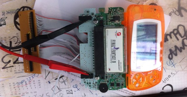
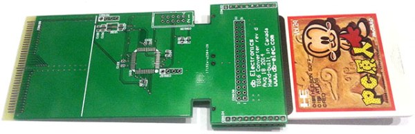
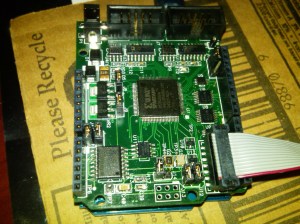
Finally, we have [Michael A. Morris] with Chameleon. Chameleon is an Arduino compatible FPGA board with a Xilinx Spartan 3A FPGA on-board. [Michael] designed Chameleon for two major purposes:  soft-core processors, and intelligent serial communications interface. On the processor side Chameleon really shines. [Michael] has implemented a 6502 core in his design. This means that it would be right at home as the core of a retrocomputing project. [Michael] is still hard at work on Chameleon, he’s recently gotten fig-FORTH 1.0 running! Nice work [Michael]!

Want more programmable logic goodness? Check out our Programmable Logic List!

That about wraps things up for this episode of The Hacklet! As always, see you next week. Same hack time, same hack channel, bringing you the best of Hackaday.io!

Direct Digital Synthesis (DDS)

Direct Digital Synthesis (DDS) Explained By [Bil Herd]

One of the acronyms you may hear thrown around is DDS which stands for Direct Digital Synthesis. DDS can be as simple as taking a digital value — a collection of ones and zeroes — and processing it through a Digital to Analog Converter (DAC) circuit. For example, if the digital source is the output of a counter that counts up to a maximum value and resets then the output of the DAC would be a ramp (analog signal) that increases in voltage until it resets back to its starting voltage.

This concept can be very useful for creating signals for use in a project or as a poor-man’s version of a signal or function generator. With this in mind I set out here to demonstrate some basic waveforms using programmable logic for flexibility, and a small collection of resistors to act as a cheap DAC. In the end I will also demonstrate an off-the-shelf and inexpensive DDS chip that can be used with any of the popular micro-controller boards available that support SPI serial communication.

All of the topics covered in the video are also discussed further after the break.

Continue reading “Direct Digital Synthesis (DDS) Explained By [Bil Herd]”

RasPiCommPlus, An Expansion Board For Expansion Boards

The easiest way to connect a GSM module to a Raspberry Pi would be to buy a breakout module, install some software, and connect to a mobile network with a Pi. Need GPS, too? That’s a whole other module, with different software. The guys behind RasPiCommPlus are working on a better solution – a breakout board for breakout boards that takes care of plugging a ton of modules into a Pi and sorts out the kernel drivers to make interfacing with these modules easy.

Right now, the team has a GPS and GSM module, digital in and out modules, an analog input module, and RS-232 and -485 modules. They’re working on some cool additions to the lineup, including a breakout for Sharp memory displays, a 9-axis IMU, a stepper motor driver, and a 1-wire breakout module.

Some of the RasPiCommPlus team showed up to the Hackaday Munich party and were kind enough to sit down for a demo video. You can check that out below.

Continue reading “RasPiCommPlus, An Expansion Board For Expansion Boards”

Breadboarding A 68000 Computer In Under A Week

We’ve been lurking over at Big Mess ‘o Wires as [Steve] geared up for his 68000 computer build. One of his previous posts mentioned a working breadboard version but we figured it would be a ways off. Surprise, he’s got it working and what you see above took just 6 days of “occasional work” to get running.

The chip in use is actually a 68008 but we remember reading that he does plan to migrate to a 68000 because this one lacks the memory pins to address more than 1 MB of RAM. The trick here was just to get the thing running and he made some common choices to get there. For instance, he grounded the /DTACK in much the same way [Brian Benchoff] explained in his own 68k build.

We’re not sure if his address decoding was a time saver or not. If you study [Steve’s] original planning post you’ll learn that he’s going to use programmable logic to handle the address decoding. But above he wired up 74-series logic chips to perform these functions. On the one hand you know your Hardware Description Language isn’t the problem, but did you terminate one of those wires where you ought not?

Additional tripping points include a bouncing reset pin. Looking at that we’d tell [Steve] there’s a problem with his chip, except that this was his first thought as well. He went the extra mile by building and testing a replica of the reset system. This makes our brain spin… shouldn’t the reset be among the most reliable parts of a processor?

At any rate, great work so far. We can’t wait to see where this goes and we hope that it unfolds in a way that is as exciting as watching [Quinn Dunki’s] Veronica project take shape.

A Proof Of Concept Flash Cart For The WonderSwan

Unless you’ve been to Japan or are fairly deep into the retro game collecting, you’ve probably never heard of the WonderSwan. It’s a handheld console, released after the Game Boy Color was beginning to show its age, and a bit before the introduction of the Game Boy Advance. It sold rather well in the only country it was released in, the game library is somewhat impressive, and there are quite a few homebrew games. Actually running these homebrew games is a challenge, though: each WonderSwan has a memory controller that maps the game ROM into the CPU’s memory. Without knowing how this controller chip works, the only way to run a homebrew cartridge is to turn on the machine with a real cart, go to the system menu, and swap the carts out. It turns out there’s a better solution, that includes programming CPLDs and looking at the output of a logic analyzer.

The first step towards [Godzil]’s efforts to create a Flash cart for the WonderSwan is to figure out the pinout of the cartridge connector – something that isn’t well documented for a system without a homebrew hardware scene. This was done in the usual way; with a lot of ribbon cable and patience This only provided an incomplete picture of how the WonderSwan interfaced with its carts, but after digging up an official development board, [Godzil] was able to make sense of all the signals.

After building a breakout board for the cartridge port, [Godzil] connected a DE0 Nano FPGA board and looked at all the signals. With just a little bit of VHDL, the memory controller could be reverse engineered and reimplemented. [Godzil] has his proof of concept working – video below – and the next part of his project will be to turn this into a proper Flash cart.

Continue reading “A Proof Of Concept Flash Cart For The WonderSwan”

A PC Engine To TurboGrafx-16 Converter

The PC Engine was pretty popular in Japan, but only the coolest kids in America had the US edition, the TurboGrafx16. These two systems weren’t exactly the same; the TurboGrafx-16’s data bus was flipped so the games were made to be incompatible, and the US games have a region lockout. [Kaz] looked at the existing hacks for running Japanese games on US systems, and every single one of them required modding a console. Thinking he could do better, he came up with the PC-Henshin, an adapter and CPLD that allows Japanese game to run on US consoles.

To take care of the mixed up lines on the PC card connector between the US and Japanese variants, a few adapter cards are available. That’s great, but they only solve one part of the compatibility problem. The region lockout routine found on nearly every American title mean PC Engine consoles can’t run TurboGrafx-16 games. [Kaz] used a small, cheap CPLD to read the data bus, patch everything as it is read out, and turns a Japanese console into something that can play American games.

Video below.

Continue reading “A PC Engine To TurboGrafx-16 Converter”