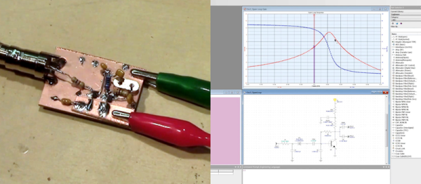
[Craig] wanted to build a 19.2 MHz crystal oscillator. He knew he wanted a Pierce oscillator, but he also knew that getting a good design is often a matter of trial and error. He used a 30-day trial of a professional simulation package, Genesys from Keysight, to look at the oscillator’s performance without having to build anything. He not only did a nice write up about his experience, but he also did a great video walkthrough (see below).
The tool generates a sample schematic, although [Craig] deleted it and put his own design into the simulator. By running simulations, he was able to look at the oscillator’s performance. His first cut showed that the circuit didn’t meet the Barkhausen criteria and shouldn’t oscillate. Unfortunately, his prototype did, in fact, oscillate.
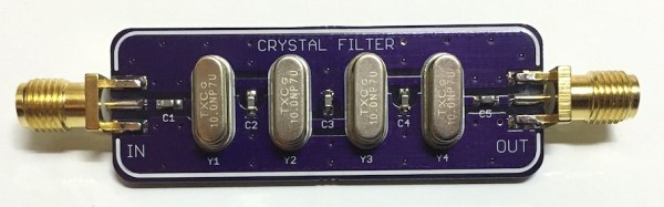
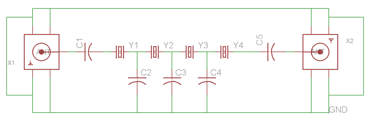
Most hobbyists use crystals as an external clock signal for a microcontroller. A less common use would be to make a bandpass filter (BPF) for an RF signal. [Dan Watson] explains his crystal ladder design on his blog and links to several sources for understanding the theory and creating your own crystal ladder band pass filter. If you want a set of these purple PCBs you can order them straight from the purple fab.
[Dan]’s schematicOne of the sources that [Dan] cites is [Larry Benko]’s personal site which is primarily dedicated to amateur radio projects. Which you can find much more in-depth information regarding the design of a xtal BPF. [Larry] goes into detail about the software he uses and some of the applications of crystal ladder filters.
BPF designed by [Larry]The process includes measuring individual xtals to determine which ones will work together for your target frequency. [Larry] also walks you through the software simulation process using LTSpice. If you aren’t familiar with Spice simulation you can get caught up by checking out the series of Spice articles by our very own [Al Williams].
The laptop I’m using, found for 50 bucks in the junk bins of Akihabara has a CPU that runs at 2.53GHz. Two billion five hundred and thirty million times every second electrons systematically briefly pulse. To the human mind this is unimaginable, yet two hundred years ago humanity had no knowledge of electrical oscillations at all.
There were clear natural sources of oscillation of course, the sun perhaps the clearest of all. The Pythagoreans first proposed that the earth’s rotation caused the suns daily cycle. Their system was more esoteric and complex than the truth as we now know it and included a postulated Counter-Earth, lying unseen behind a central fire. Regardless of the errors their theory contained, a central link was made between rotation and oscillation.
And rotational motion was exploited in early electrical oscillators. Both alternators, similar to those in use today, and more esoteric devices like the interrupter. Developed by Charles Page in 1838, the interrupter used rocking or rotational motion to dip a wire into a mercury bath periodically breaking a circuit to produce a simple oscillation.
As we progressed toward industrial electrical generators, alternating current became common. But higher and higher frequencies were also required for radio transmitters. The first transmitters had used spark gaps. These simple transmitters used a DC supply to charge a capacitor until it reached the breakdown voltage of the gap between two pieces of wire. The electricity then ionized the air molecules in the gap. Thus allowing current to flow, quickly discharging the capacitor. The capacitor charged again, allowing the process to repeat.
As you can see and hear in the video above spark gaps produce a noisy, far from sinusoidal output. So for more efficient oscillations, engineers again resorted to rotation.
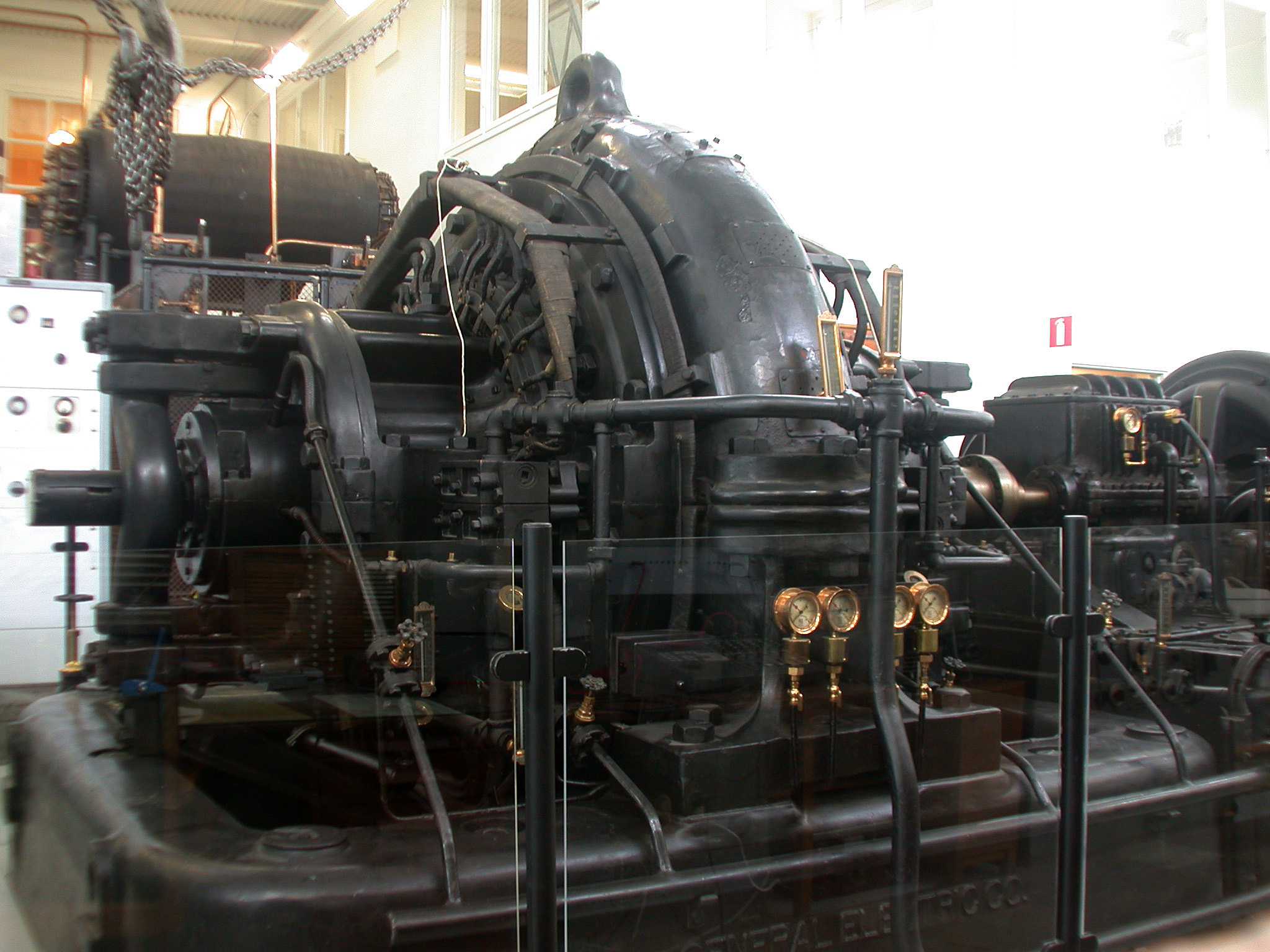
The Alexanderson alternator uses a wheel on which hundreds of slots are cut. This wheel is placed between two coils. One coil, powered by a direct current, produces a magnetic field inducing a current in the second. The slotted disc, periodically cutting this field, produces an alternating current. Alexanderson alternators were used to generate frequencies of 15 to 30 KHz, mostly for naval applications. Amazingly one Alexanderson alternator remained in service until 1996, and is still kept in working condition.
A similar principal was used in the Hammond organ. You may not know the name, but you’ll recognize the sound of this early electronic instrument:
The Hammond organ used a series of tone wheels and pickups. The pickups consist of a coil and magnet. In order to produce a tone the pickup is pushed toward a rotating wheel which has bumps on its surface. These are similar to the slots of the Alexanderson Alternator, and effectively modulate the field between the magnet and the coil to produce a tone.
Amplifying the Oscillation
The operation of a tank circuit (from wikipedia)
So far we have purely relied on electromechanical techniques, however amplification is key to all modern oscillators, for which of course you require active devices. The simplest of these uses an inductor and capacitor to form a tank circuit. In a tank circuit energy sloshes back and forth between an inductor and capacitor. Without amplification, losses will cause the oscillation to quickly die out. However by introducing amplification (such as in the Colpitts oscillator) the process can be kept going indefinitely.
Oscillator stability is important in many applications such as radio transmission. Better oscillators allow transmissions to be packed more closely on the spectrum without fear that they might drift and overlap. So the quest for better, more stable oscillators continued. Thus the crystal oscillator was discovered, and productionized. This was a monumental effort.
Producing Crystal Oscillators
The video below shows a typical process used in the 1940s for the production of crystal oscillators:
Natural quartz crystals mined in Brazil were shipped to the US, and processed. I counted a total of 13 non-trivial machining/etching steps and 16 measurement steps (including rigorous quality control). Many of these quite advanced, such as the alignment of the crystal under an X-Ray using a technique similar to X-Ray crystalography.
These days our crystal oscillator production process is more advanced. Since the 1970s crystal oscillators have been fabricated in a photolithographic process. In order to further stabilize the crystal additional techniques such as temperature compensation (TCXO) or operating the crystal at a temperature controlled by the use of a heating element (OCXO) have been employed. For most applications this has proved accurate enough… Not accurate enough however for the timenuts.
Timenuts Use Atoms
Typical timenut wearing atomic wristwatch
For timenuts there is no “accurate enough”. These hackers strive to create the most accurate timing systems they can, which all of course rely on the most accurate oscillator they can devise.
Many timenuts rely on atomic clocks to make their measurements. Atomic clocks are an order of magnitude more precise than even the best temperature controlled crystal oscillators.
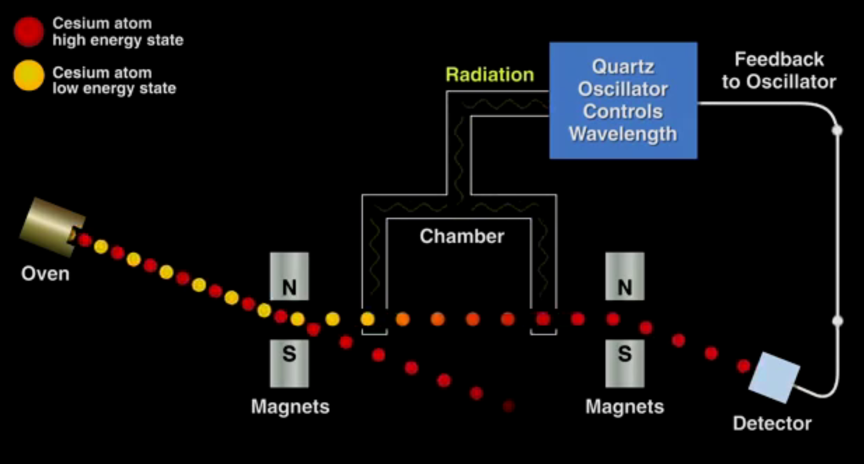
Bill Hammack has a great video describing the operation of a cesium beam oscillator. The fundamental process is shown in the image below. The crux is that cesium gas exists in two energy states, which can be separated under a magnetic field. The low energy atoms are exposed to a radiation source, the wavelength of which is determined by a crystal oscillator. Only a wavelength of exactly 9,192,631,770Hz will convert the low energy cesium atoms to the high energy form. The high energy atoms are directed toward a detector, the output of which is used to discipline the crystal oscillator, such that if the frequency of the oscillator drifts and the cesium atoms are no longer directed toward the detector its output is nudged toward the correct value. Thus a basic physical constant is used to calibrate the atomic clock.
The basic operating principle of a cesium atomic clock
While cesium standards are the most accurate oscillators known, Rubidium oscillators (another “atomic” clock) also provide an accurate and relatively cheap option for many timenuts. The price of these oscillators has been driven down due to volume production for the telecoms industry (they are key to GSM and other mobile radio systems) and they are now readily available on eBay.
With accurate time pieces in hand timenuts have performed a number of interesting experiments. To my mind the most interesting of these is measuring time differences due to relativistic effects. As is the case with one timenut who took his family and a car full of atomic clocks up Mt. Rainier for the weekend. When he returned he was able to measure a 20 nanosecond difference between the clocks he took on the trip and those he left at home. This time dilation effect was almost exactly as predicted by the theory of relativity. An impressive result and an amazing family outing!
It’s amazing to think that when Einstein proposed the theory of special relatively in 1905, even primitive crystal oscillators would not have been available. Spark gap, and Alexanderson alternators would still have been in everyday use. I doubt he could imagine that one day the fruits of his theory would be confirmed by one man, on a road trip with his kids as a weekend hobby project. Hackers of the world, rejoice.
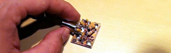
Ever wonder how a crystal oscillator works? How does that little metal can with a sliver of quartz start vibrating to produce a clock signal for just about everything we use, while doing it in the accuracy range in the parts per million and cost practically nothing?
Well [Craig] decided its about time for an in depth tutorial that covers everything you need to know to understand, design, and construct your very own. Wrapped up in a 41 minute video, [Craig] covers the absolute basic theories and designs, math, datasheet explanation of crystals, and even a practical example of a Pierce crystal oscillator, suitable for use in a HF transceiver. Now you can make your own for your own application no matter if you’re just trying to save a pin on your favorite micro, or making a radio transceiver.
With this wealth of knowledge, whether you are learning for the first time, or just need a refresher, you should join us after the break, kick back and check out this highly informative video.
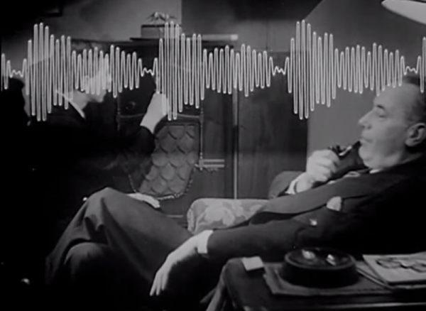
Many of us still tune in to terrestrial radio for one reason or another, be it baseball games, talk radio, or classic rock. But do you know how the sound is transmitted to your receiver? This week, our spotlight shines upon a short film produced by KYW Radio that serves as a cheerful introduction to the mysteries of amplitude modulation (AM) radio transmission as they were in 1940.
Sound vibrations enter a microphone and are converted to electrical current, or an audio waveform. The wave is amplified and sent several miles away to the transmitting station. During this trip, the signal loses power and so is amplified at the transmitting station in several stages. This audio wave can’t be transmitted by itself, though; it needs to catch a ride on a high-frequency carrier wave. This wave is generated on-site with a huge crystal oscillator, then subjected to its own series of amplifications prior to broadcast.
The final step is the amplitude modulation itself. Here, the changing amplitude of the original audio wave is used to modulate that of the high-frequency carrier wave. Now the signal is ready to be sent to the tower. Any receiver tuned in to the carrier frequency and in range of the signal will capture the carrier wave. Within the reciever, these currents are converted back to the vibrations that our ears know and love.
The first order of business in making something with the chip is to establish a clock signal. She sourced a crystal oscillator which runs at 1 MHz, but also wanted the option to single step through code. Her solution was to build two clock signals in one. A toggle switch allows her to choose the crystal, or a 555 timer circuit which uses a push button to fire each clock pulse.
Check out the video after the break to see some single stepping action. There’s no memory on board just yet. But the input pins have been hard-wired to voltage or ground to simulate data input. We wondered what she was up to with that HEX Out project which stiffs the logic on the data bus. Looks like it’s extremely useful in this project!
[Paul] has been working on porting over Arduino libraries for use with the Teensy microcontroller platform. This tends to be pretty simple since they both use the same Atmel chip architecture. But once in a while he finds the Arduino libraries are not what they’re cracked up to be. When looking to port over a frequency measurement library he ended up writing his own that works better and is much more portable.
He had two big beefs with the Arduino Frequency Counter Library. The first is that it required the compensation factor the be calibrated using an accurate frequency counter. That’s a chick-and-egg problem since many people who build a frequency counter with an Arduino are doing so because they don’t already have a standalone tool. The second problem is that the Arduino library was hardcoded for ATmega168 or ATmega328 chips.
This new library fixes both issues with just one trade-off. Your hardware setup must be using a crystal oscillator. You can see above in the image above that the frequency measurement is quite accurate with this method. The package also uses a thin abstraction layer which will make it easy to port to any 8-bit microcontroller which is programmed in C.
![BPF designed by [Larry]](https://hackaday.com/wp-content/uploads/2016/03/20m_xtalbp_s21close_7-23-2009.gif)