Proper Routing Makes For Many Happy Return Paths

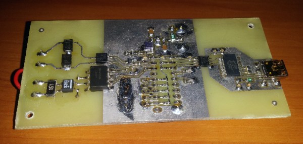
Here’s a question for you: when your PCB has a ground plane layer, where do return signals flow? It seems like a trick question, but as [Kristof Mulier] explains, there’s more to return path routing (alternate link in case you run into a paywall) than just doing a copper pour and calling it a day.

Like so many other things in life, the answer to the above question is “it depends,” and as [Kristof] ably demonstrates in this concise article, the return path for a signal largely depends on its frequency. He begins by explaining current loop areas and how they factor into the tendency for a circuit to both emit and be susceptible to electromagnetic noise. The bigger the loop area, the worse things can get from a noise perspective. At low frequencies, return signals will tend to take the shortest possible path, which can result in large current loop areas if you’re not careful. At higher frequencies, though, signals will tend to follow the path of minimal energy instead, which generally ends up being similar to the signal trace, even if it has a huge ground plane to flow through.

Since high-frequency signals naturally follow a path through the ground plane that minimizes the current loop, that means the problem takes care of itself, right? It would, except that we have a habit of putting all kinds of gaps in the way, from ground plane vias to isolation slots. [Kristof] argues that this can result in return paths that wiggle around these features, increasing the current loop area to the point where problems creep in. His solution? Route all your signal return paths. Even if you know that the return traces are going to get incorporated into a pour, the act of intentionally routing them will help minimize the current loop area. It’s brilliantly counterintuitive.

This is the first time we’ve seen the topic of high-frequency return paths tackled. This succinct demonstration shows exactly how return path obstructions can cause unexpected results.

Thanks to [Marius Heier] for the tip.

Simple Circuit Keeps Process Control Loops In Tune

Spare a moment’s pity for the process engineer, whose job it is to keep industrial automation running no matter what. These poor souls seem to be forever on call, fielding panicked requests to come to the factory floor whenever the line goes down. Day or night, weekends, vacations, whatever — when it breaks, the process engineer jumps.

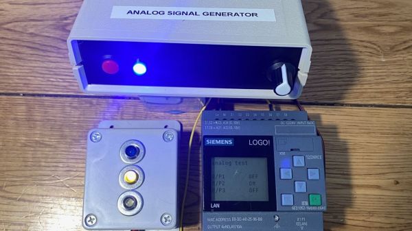
The pressures of such a gig can be enormous, and seem to have weighed on [Tom Goff] enough that he spent a weekend building a junk bin analog signal generator to replace a loop calibrator that he misplaced. Two process control signaling schemes were to be supported — the 0 to 10 VDC analog signal, and the venerable 4-20 mA current loop. All that’s needed for both outputs is an Arduino and an LM358 dual op-amp, plus a few support components. The 0-10 V signal starts as a PWM output from the Arduino, with its 0-5 V average amplified by one of the op-amps set up as a non-inverting amp with a gain of 2. With a little filtering, the voltage output is pretty stable, and swings nicely through the desired range — see the video below for that.

The current loop output is only slightly more complicated. An identical circuit on a separate Arduino output generates the same 10 V max output, but a code change limits the low end of the range to 1 V. This output of the op-amp is fed through a 500-Ω trimmer pot, and the magic of Ohm’s Law results in a 4-20 mA current. The circuit lives on a piece of perf board in a small enclosure and does the job it was built for — nothing fancy needed.

And spoiler alert: [Tom] found the missing loop calibrator — after he built this, of course. Isn’t that always the way?

Continue reading “Simple Circuit Keeps Process Control Loops In Tune”

Current Loop Extends Wired Microphones Past 1 Km

A problem which beset early telephone engineers was that as the length of their lines increased, so did the distortion of whatever signal they wanted to transmit. This was corrected once they had gained an understanding of the capacitance and inductance of a long cable. The same effects hamper attempts to place microphones on long lines, and [Leo’s Bag of Tricks] has a solution for doing that using Cat5 cable. The application is audio surveillance, but we think the technique is useful enough to have application elsewhere.

The solution which you can see in the video below the break will be familiar to teletype aficionados who have encountered current loops, in that it creates an analogue current loop. There is a standing DC current in the tens of miliamperes, and this has the audio imposed upon it by an amplifier and  shunt transistor. The audio can be easily retrieved using a pair of small transformers, leading to efficient transfer over as much of a kilometer of Cat5 cable. We’re guessing it’s not quite audiophile quality, but it’s useful to know that a current loop can be just as useful in the analogue domain as in the digital. If the subject interests you, we did a feature on them a few years ago.

Continue reading “Current Loop Extends Wired Microphones Past 1 Km”

Logging Into Linux With A 1930s Teletype

Buried deep within all UNIX-based operating systems are vestiges of the earliest days of computing, when “hardware” more often than not meant actual mechanical devices with cams and levers and pulleys and grease. But just because UNIX, and by extension Linux, once supported mechanical terminals doesn’t mean that getting a teletype from the 1930s to work with it is easy.

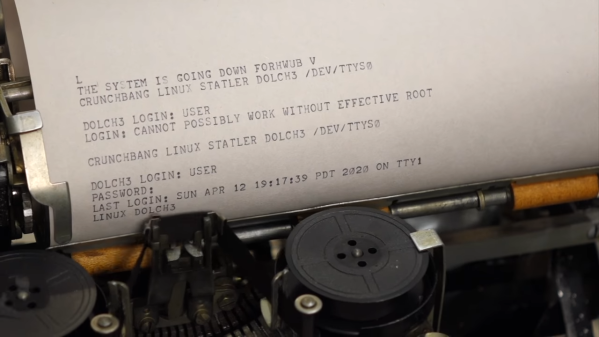
Such was the lesson learned by [CuriousMarc] with his recently restored Model 15 Teletype; we covered a similar Model 19 restoration that he tackled. The essential problem is that the five-bit Baudot code that they speak predates the development of ASCII by several decades, making a converter necessary. A task like that is a perfect job for an Arduino — [Marc] put a Mega to work on that — but the interface of the Teletype proved a bit more challenging. Designed to connect two or more units together over phone lines, the high-voltage 60-mA current loop interface required some custom hardware. The testing process was fascinating, depending as it did on an old Hewlett-Packard serial signal generator to throw out a stream of five-bit serial pulses.

The big moment came when he used the Teletype to log into Linux on a (more or less) modern machine. After sorting out the mysteries of the stty command, he was able to log in, a painfully slow process at 45.5 bps but still a most satisfying hack. The ASCII art — or is it Baudot art? — is a nice bonus.

We love restorations like these, and can practically smell the grease and the faint tang of ozone around this device. We’re not thrilled by the current world situation, but we’re glad [CuriousMarc] was able to use the time to bring off a great hack that honors another piece of our computing history.

Continue reading “Logging Into Linux With A 1930s Teletype”

Texting With A Teletype

How do you get the kids interested in old technology? By connecting it to a phone, obviously. Those kids and their phones. When [Marek] got his hands on an old-school teletype, he hooked it up to a GSM network, with all the bells and whistles including a 40mA current loop running at an impressive 50 baud.

The teletype in question here is a vintage T100 teletype manufactured in Czechoslovakia sometime in the ’70s. This was a gift to [Marek]’s workplace, the museum of Urban Engineering in Cracow, and this project is effectively an experiment to investigate the possibility of running this teletype as an interactive exhibit rather than an artefact from the age of current loops and phone systems.

The current loop is, or was, the standard way of connecting a teletype to anything, so all [Marek] had to do was construct a box that translated the signals from a GSM modem to this current loop. For the prototype, the microcontroller in question is an old AT89C2051 (as that’s what was sitting in the parts drawer). This was moved over to a PIC32 microcontroller and a SIM800 GSM module. This is housed in a two-part enclosure, with the GSM interfaced housed in one half, with the current loop generator consisting of a simple DC power supply housed int the other half.

This interface is capable of receiving and sending messages from the keyboard to a GSM network, so it is theoretically possible you could text your friends using an old-school teletype. This functionality hasn’t been implemented yet, but it is just about the coolest thing you could possibly imagine. You can check out a video of the teletype in action below. Continue reading “Texting With A Teletype”

A Switching Power Supply, 1940s-Style

“They don’t build ’em like they used to.” There’s plenty of truth to that old saw, especially when a switch-mode power supply from the 1940s still works with its original parts. But when said power supply is about the size of a smallish toddler and twice as heavy, building them like the old days isn’t everything it’s cracked up to be.

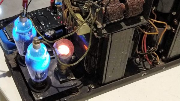
The power supply that [Ken Shirriff] dives into comes from an ongoing restoration of a vintage teletype we covered recently. In that post we noted the “mysterious blue glow” of the tubes in the power supply, which [Ken] decided to look into further. The tubes are Thyratrons, which can’t really be classified as vacuum tubes since they’re filled with various gasses. Thyratrons are tubes that use ionized gas – mercury vapor in this case – to conduct large currents. In this circuit, the Thyratrons are used as half-wave rectifiers that can be rapidly switched on and off by a feedback circuit. That keeps the output voltage fixed at the nominal 140V DC required by the teletype, with a surprisingly small amount of ripple. The video below is from a series on the entire restoration; this one is cued to where the power supply is powered up for the first time. It’s interesting to see the Thyratrons being switched at about 120 Hz when the supply is under load.

Cheers to [Ken] and his retrocomputing colleagues for keeping the old iron running. Whether the target of his ministrations is a 1974 scientific calculator or core memory from an IBM 1401, we always enjoy watching him work.

Continue reading “A Switching Power Supply, 1940s-Style”

The 4-20 MA Current Loop

The I/O capabilities built into most microcontrollers make it easy to measure the analog world. Say you want to build a data logger for temperature. All you need to do is get some kind of sensor that has a linear voltage output that represents the temperature range you need to monitor — zero to five volts representing 0° to 100°C, perhaps. Hook the sensor up to and analog input, whip up a little code, and you’re done. Easy stuff.

Now put a twist on it: you need to mount the sensor far from the microcontroller. The longer your wires, the bigger the voltage drop will be, until eventually your five-volt swing representing a 100° range is more like a one-volt swing. Plus your long sensor leads will act like a nice antenna to pick up all kinds of noise that’ll make digging a usable voltage signal off the line all the harder.

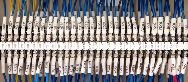
Luckily, industrial process engineers figured out how to deal with these problems a long time ago by using current loops for sensing and control. The most common standard is the 4-mA-to-20-mA current loop, and here we’ll take a look at how it came to be, how it works, and how you can leverage this basic process control technique for your microcontroller projects.

Continue reading “The 4-20 MA Current Loop”