Inside A Current Probe

[The Signal Path] had two Tektronix AC/DC current probes that didn’t work. Of course, that’s a great excuse to tear them open and try to get at least one working. You can see how it went in the video below. The symptoms differed between the two units, and along the way, the theory behind these probes needs some exploration.

The basic idea is simple, but, of course, the devil is in the details. A simple transformer doesn’t work well at high frequencies and won’t work at all at DC. The solution is to use a hall effect sensor to measure DC and also to feed it back to cancel coil saturation.

Continue reading “Inside A Current Probe”

Cheap Current Probe Gets Good Review

A current probe isn’t a very common fixture on most workbenches because they are pretty expensive. [VoltLog] looks at a fairly inexpensive current probe from Micsig. He seemed impressed with the workmanship and it looks similar to more expensive offerings. There are two models with different bandwidth numbers (800 kHz and 2 MHz). It can measure current on a 10A and 100A scale.

According to [VoltLog] comparable probes from other vendors are more expensive and have lower bandwidth. He also liked that the device powers from USB since most newer scopes will have a USB port available.

Continue reading “Cheap Current Probe Gets Good Review”

Flux Gate Magnetometers Make A Special Current Probe

There are moments when current measurement is required on conductors that can’t be broken to insert a series resistor, nor encircled with a current transformer. These measurements require a completely non-invasive technique, and to satisfy that demand there are commercial magnetometer current probes. These probes are however not for the light of wallet, so [ensgoldmine] has created a much cheaper alternative.

The Texas Instruments GRV425 flux gate magnetometer integrated circuit on its TI evaluation module provides the  measuring element placed at the tip of a probe as close as possible to the conductor to be measured, with another GRV425 module at the head of the probe to measure ambient magnetic field for calibration purposes.  An Arduino Due measures and processes the readings, chosen due to its higher-resolution ADC than the more ubiquitous Arduino Uno.

The write-up is interesting even if you have no need for a current probe, because of its introduction to these sensing elements. Because it’s a rare first for Hackaday, we’ve never taken a close look at them before other than as an aside when talking about a scientific instrument on Mars.

Make Your Own Current Clamp Probe

If you want to measure AC or DC current with an oscilloscope, a current clamp is a great way to do it. The clamp surrounds the wire, so you don’t need to break the connection to take your measurements. These used to be expensive, although we’ve seen some under $100, if you shop. We don’t know if it was cost or principle that motivated [Electronoobs] to build his own current clamp, but he did.

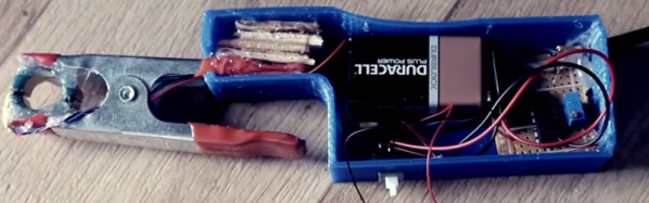
This probe design is little more than a 3D printed case, an old power supply toroid, and a conventional alligator clamp to make the business end. The sensor uses a ferrite core and a hall effect sensor. The ferrite toroid is split in half, one half in each side of the clamp. An opamp circuit provides a gain of 100 to boost the hall effect sensor’s output.

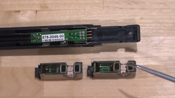
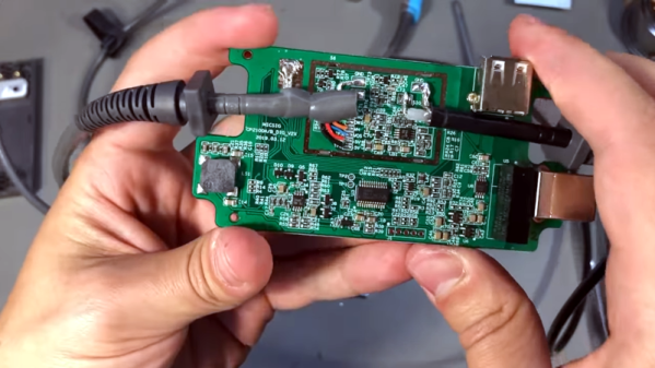
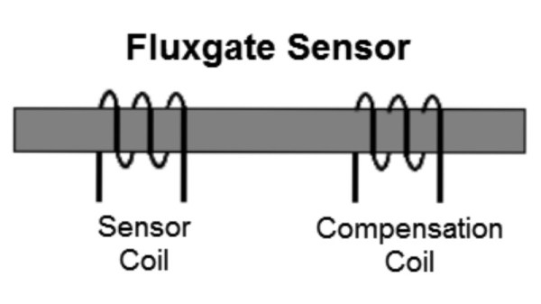
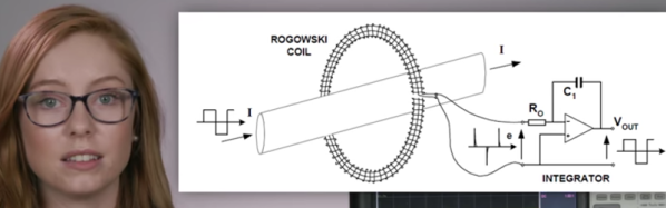
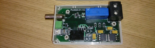
In addition to building a homebrew probe, the video also shows a teardown of a Hantek current probe and explains the theory behind the different kinds of current probes, including some tricks like using a compensation winding to prevent core magnetization.

Does it work? You bet. After calibration, it did just fine. It’s not as pretty as a $100 unit, but beauty is in the eye of the beholder, and we are suckers for homebrew gear so we will say it is certainly more interesting. If you have a fair junk box (and a 3D printer), this probe could be made very inexpensively. The hall effect and a BNC connector are likely to be the most expensive parts. Even if you bought everything and used a non-printed case, we would be hard-pressed to think you’d spend more than $25.

If you want to see how the big boys do it, Keysight had a good break down last year. We’ve seen other homebrew builds for current probes and some of them are very accurate.

Continue reading “Make Your Own Current Clamp Probe”

Current Measurement With Oscilloscopes

What do a Rogowski coil, a magnetic core, and a hall effect sensor have in common? They are all ways you can make oscilloscope probes that measure current. If you think of a scope as a voltage measurement device, you ought to watch the recent video from Keysight Technology (see below). It is true that Keysight would love to sell you a probe, but the video is not a sales pitch, just general technical information about making current measurements with an oscilloscope.

Of course, you can always measure the voltage across a shunt resistor — either one that is naturally in the circuit or one you’ve put inline just for measuring purposes. But if you add a resistor it will change the circuit subtly and it may have to handle a lot of power.

The Keysight video points out that there are different probes for different current measurement regimes. High current, medium current, and low current all use different probes with different technologies. The video is only about 6 minutes long and if you’ve never thought about measuring current with a scope, it is worth watching.

The video shares some high-level details of how the current probes work — that’s where the Rogowski coil comes in, for example. Of course, you can’t expect a vendor to tell you how to build your own current probes. That’s OK, though, because we will. Current probes are often expensive, but you can sometimes pick up a deal on a used one.

Continue reading “Current Measurement With Oscilloscopes”

A Very Accurate Current Probe

There’s many different ways of measuring current. If it’s DC, the easiest way is to use a shunt resistor and measure the voltage across it, and for AC you could use a current transformer. But the advent of the Hall-effect sensor has provided us a much better way of measuring currents. Hall sensors offers several advantages over shunts and CT’s – accuracy, linearity, low temperature drift, wider frequency bandwidth, and low insertion loss (burden) being some of them. On the flip side, they usually require a (dual) power supply, an amplification circuit, and the ability to be “zero adjusted” to null output voltage offsets.

[Daniel Mendes] needed to measure some fairly high currents, and borrowed a clip-on style AC-DC current probe to do some initial measurements for his project. Such clip on current probes are usually lower in accuracy and require output DC offset adjustments. To overcome these limitations, he then built himself an invasive hall sensor current probe to obtain better measurement accuracy (Google Translated from Portugese). His device can measure current up to 50 A with a bandwidth stretching from DC to 200 kHz. The heart of his probe is the LAH-50P hall effect current transducer from LEM – which specialises in just such devices. The 25 mV/A signal from the transducer is buffered by an OPA188 op-amp which provides a low output impedance to allow interfacing it with an oscilloscope. The op-amp also adds a x2 gain to provide an output of 50 mV/A. The other critical part of the circuit are the high tolerance shunt resistors connected across the output of the LAH-50P transducer.

The rest of his design is what appears to be a pretty convoluted power supply section. [Daniel] wanted to power his current probe with a 5V input derived from the USB socket on his oscilloscope. This required the use of a 5 V to 24 V boost switching regulator – with two modules being used in parallel to provide the desired output power. A pair of linear regulators then drop down this voltage to +15 / -15 V required for the trasducer and op-amp. His blog post does not have the board layout, but the pictures of the PCB should be enough for someone wanting to build their own version of this current sensor.

Teardown A Classic : Tektronix P6042 Current Probe

[Paul Rako]’s teardown of his treasured P6042 current probe shows why Tektronix commands so much respect among the old hats of the electronics world.

Built in 1969, the P6042 is pretty sparse transistor-wise when compared a modern sensor. The user would clip the current probe, permanently attached to the case since the circuit was tuned for each one, over a wire and view the change in volts on an oscilloscope. When the voltage division on the oscilloscope was set properly the current in a circuit could be easily seen.

The teardown is of a working unit so it’s not completely disassembled, but it also sits as a nice guide on refurbishing your own P6043, if you manage to snag one from somewhere. Aside from capacitors and oxidized switch contacts there’s not much that can go wrong with this one.

As for how it compares, the linear power supply, analog circuit design, and general excellent engineering has the P6042 coming in with a cleaner signal than some newer models. Not bad for a relic! Do any of you have a favorite old bit of measurement kit?