Custom Isolated Variac Is Truly One Of A Kind

It’s no surprise that many hardware hackers avoid working with AC, and frankly, we can’t blame them. The potential consequences of making a mistake when working with mains voltages are far greater than anything that can happen when you’re fiddling with a 3.3 V circuit. But if you do ever find yourself leaning towards the sparky side, you’d be wise to outfit your bench with the appropriate equipment.

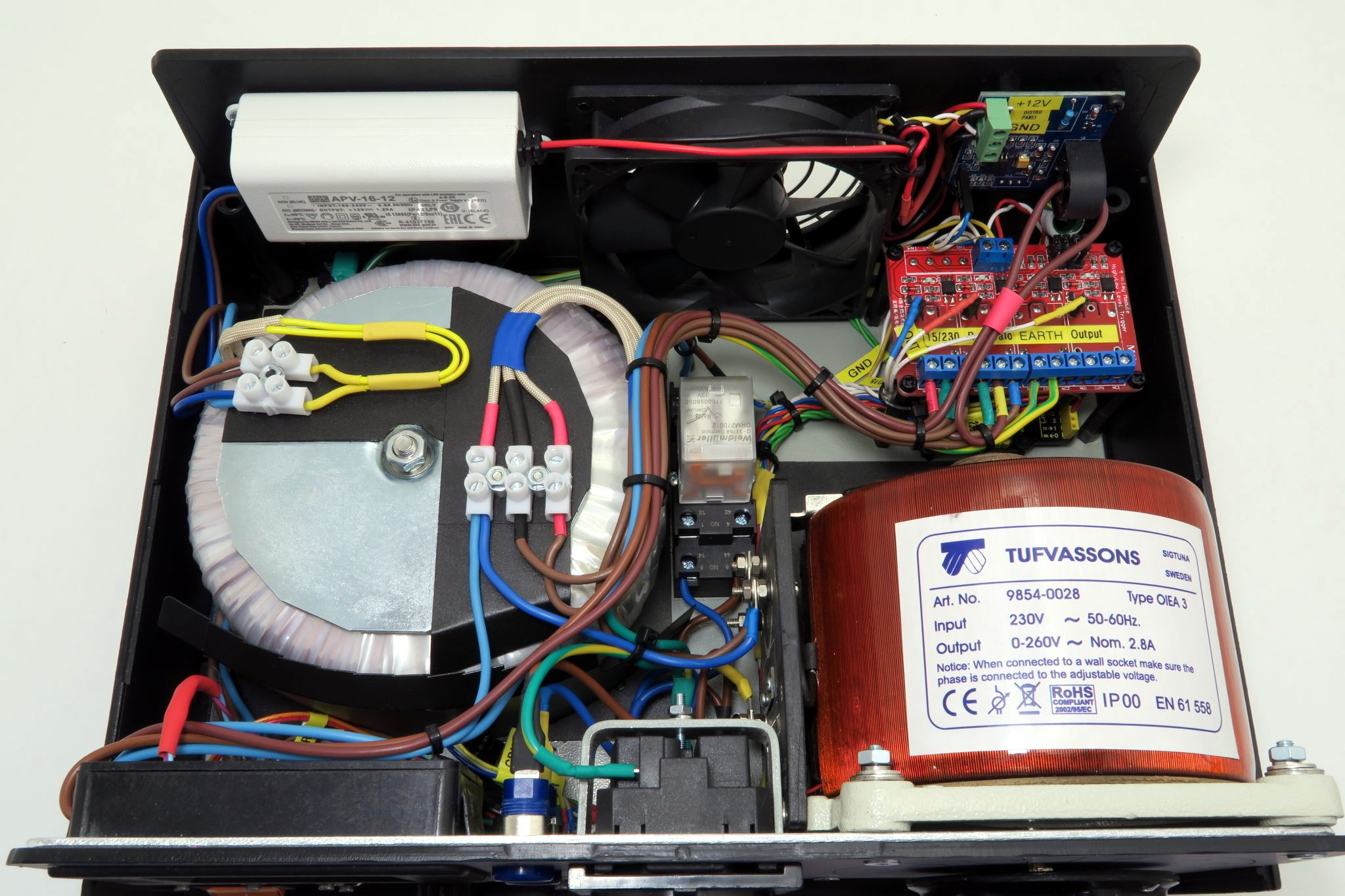
Take for example this absolutely gorgeous variable isolation transformer built by [Lajt]. It might look like a  high-end piece of professional test equipment, but as the extensive write-up and build photographs can attest, this is a completely custom job. The downside is that this particular machine will probably never be duplicated, especially given the fact its isolation transformer was built on commission by a local company, but at least we can look at it and dream.

This device combines two functions which are particularly useful when repairing or testing AC hardware. As a variable transformer, often referred to as a variac, it lets [Lajt] select how much voltage is passed through to the output side. There’s a school of thought that says slowly ramping up the voltage when testing an older or potentially damaged device is better than simply plugging it into the wall and hoping for the best. Or if you’re like Eddie Van Halen, you can use it to control the volume of your over-sized Marshall amplifiers when playing in bars.

Image of the device's internal components.Secondly, the unit isolates the output side. That way if you manage to cross the wrong wire, you’re not going to pop a breaker and plunge your workshop into darkness. It also prevents you from accidentally blowing up any AC powered test equipment you might employ while poking around, such as that expensive oscilloscope, since the devices won’t share a common ground.

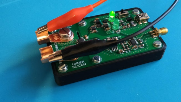
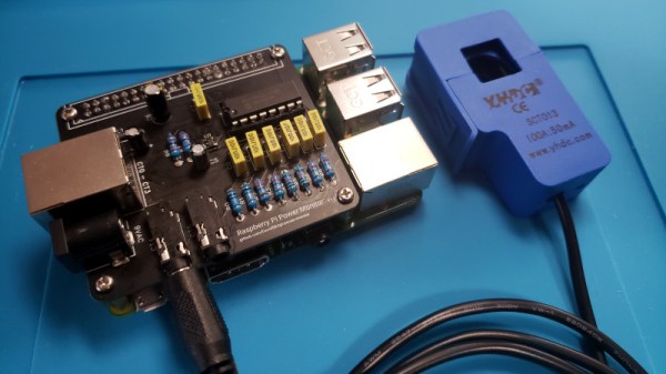
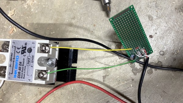
Additional safety features have been implemented using an Arduino Uno R3 clone, a current sensor, and several relays. The system will automatically cut off power to the device under test should the current hit a predetermined threshold, and will refuse to re-enable the main relay until the issue has been resolved. The code has been written in such a way that whenever the user makes a configuration change, power will be cut and must be reestablished manually; giving the user ample time to decide if its really what they want to do.

[Lajt] makes it clear that the write-up isn’t meant as a tutorial for building your own, but that shouldn’t stop you from reading through it and getting some ideas. Whether you’re in the market for custom variac tips or just want to get inspired by an impeccably well engineered piece of equipment, this project is a high-water mark for sure.

Battery Analyzer Puts Alkaline Cells To The Test

We know, we know. Generally speaking, you should try and switch your household devices over to rechargeable cells rather than using disposable alkaline batteries. But while they might seem increasingly quaint in the lithium-ion era, features such as a long shelf life make it worth keeping a pack of disposables around. So which ones should you buy? That’s what [Moragor] wanted to find out with his personal battery analyzer.

Designed as a shield for the Arduino Mega 2560, the analyzer combines a small programmable electronic load with a INA219 current sensor, OLED display, and SD card reader. The user selects the cutoff voltage and discharge rate before the test begins, and once it’s running, data is collected every second and saved to the SD card for later analysis. Once the battery voltage reaches the predetermined value, the test is over and you’re ready to put a new cell through its paces.

After testing 27 different brands of batteries, [Moragor] tabulated all the data and produced some helpful charts to illustrate the results. With few exceptions, the performance level for most of the batteries was remarkably similar. If anything, the test seemed to show that higher tier batteries from companies like Duracell and Energizer actually performed slightly worse than the mid-range offerings. Perhaps the biggest surprise is that, when the per-cell cost was factored in, the local cheapo batteries provided a better value than anything else in the test.

While the selection of battery brands may be different from where you live, the data [Moragor] collected is still a fascinating even if you don’t recognize some of the names on the chart. Of particular note is the confirmation that lithium batteries handily outperformed any of the Alkaline cells tested when it came to high-drain applications. We’d still rather they came in rechargeable form, but at least it’s a step in the right direction.

High Current Measurement Probe For Oscilloscopes

A decent current measurement sensor ought to be an essential part of every hacker’s workbench. One that is capable of measuring DC, as well as low and high frequencies with reasonable accuracy. And bonus credits if it can also withstand high bus voltages – such as those found in mains utility or electric vehicle work. [Undersilicon] couldn’t find one that ticked all the boxes, so he built an ACS730 based AC/DC current probe capable of measuring up to 25 A at frequencies up to 1 MHz.

Allegro Microsystems has a wide offering of current sensor IC’s. The ACS730 features a -3 dB bandwidth of 1 MHz, and -1 dB bandwidth of 500 kHz. Since it is galvanically isolated, it can be used in AC mains applications up to 297 Vrms and for DC up to 420 V. And as he intended to use it as an oscilloscope accessory, the analog output suited the application nicely. A pair of precision op-amps provide the voltage output scaled to 100 mV/A. The board is powered off a 1000 mAh LiPo battery that can run the sensor for about 15 ~ 20 hours. The power supply section consists of a charge circuit for the LiPo, and a split rail dual output power supply converter for the op-amps.

The ACS730 has a 2.5 V output when measured current is zero, and is scaled for 40 mV/A. This gives an output voltage swing from -0.5 V for -50 A to +4.5 V for +50 A. This is where the AD823ARZ dual 16 MHz, Rail-to-Rail FET Input Amplifiers step in. One pair is used to obtain a 2.5 V reference from the 5 V supply, and also to buffer the analog output from the ACS730. The second pair subtracts the 2.5 V offset, and applies a gain of 2.5 to get the 100 mV/A output. Dual power supply for the op-amps comes from a TPS65133 Split-Rail Converter, ±5V, 250mA Dual Output Power Supply. Lastly, LiPo charging is handled by the MCP73831 Single Cell, Li-Ion/Li-Polymer Charge Management Controller.

Initial testing of direct currents has shown fairly accurate performance. But he’s observed some noise when measuring currents below 1 A which requires some debugging to figure out the source. [Undersilicon] has provided the CAD files for both the PCB and 3D printed enclosure, giving you access to everything you need to build one yourself. If you’re looking for something a bit more heavy duty, you might be interested in this +/-50 A, 1.5 MHz sensor encased in concrete.

A Complete Raspberry Pi Power Monitoring System

As the world has become more environmentally conscious, we’ve seen an uptick in projects that monitor or control home energy use. At a minimum one of these setups involves a microcontroller and some kind of clamp-on current sensor, but if you’re looking for resources to take things a bit farther, this Raspberry Pi energy monitoring system created by [David00] would be a great place to start.

This project includes provides software and hardware to be used in conjunction with the Raspberry Pi to keep tabs on not just home energy consumption, but also production if your home has a solar array or other method of generating its own power. Data is pulled every 0.5 seconds from a MCP3008 ADC connected to up to five six current sensors to provide real-time utilization statistics, and visualized with Grafana so you can see all of the information at a glance.

While [David00] has already done the community a great service by releasing the hardware and software under an open source license, he’s also produced some absolutely phenomenal documentation for the project that’s really a valuable resource for anyone who wants to roll their own monitoring system. He’s even offering hardware kits for anyone who’s more interested in experimenting with the software side of things than building the PCB.

Home energy monitoring projects are certainly nothing new, but the incredible advances we’ve seen in the type of hardware and software available for DIY projects over the last decade has really pushed the state-of-the-art forward. With so many fantastic resources available now, the only thing standing between you and your own home energy monitoring dashboard is desire and a long weekend.

Versatile Energy Meter Has Multiple Functions

If you are dealing with solar or battery power, you might want to have one of these little energy meters built by [Open Green Energy] around. The Arduino-based instrument measures DC voltage, current, power, energy, capacity, and temperature. The range is only up to 26 volts and 3.2 amps, but you could extend that with some external circuitry.

Of course, measuring a voltage with the Arduino is old hat. But the addition of a INA219 current sensor provides voltage, current, and power measurements in a single module that talks I2C back to the host computer.

Continue reading “Versatile Energy Meter Has Multiple Functions”

Vacuum Dust Collection With Self-Powered Relays

Like many people with multiple woodworking tools, [Will Stone] wanted to create a centralized dust collection system. But he quickly found that the devil was in the details, as he struggled to find an economic way to automatically kick on the vacuum when one of the tools started up. His final solution might be one of the most elegant, and surely the cheapest, we’ve ever come across.

As with other DIY systems we’ve seen over the years, [Will] is using a simple inductive current sensor to detect when AC power is being drawn by one of his tools. But where the similarity stops is that there’s nothing so pedestrian as a microcontroller reading the output of the sensor. He realized that when the coils in the sensor were energized they were putting out about 7 volts AC, which should be more than enough to trigger a relay.

So he threw together a rectifier circuit on a piece of perfboard, using four LEDs in true hacker style. With the addition of a capacitor to smooth out the voltage, this little circuit is able to trip the 40 amp solid state relay controlling power to the vacuum using nothing more than the energy harvested from the sensor’s coil.

Using a current sensor is great when the tools are close enough to all be plugged into the same line, but that doesn’t help the folks with cordless tools or supersized shops. In that case, you might need to look into a sound-activated system.

The Easiest Way To Put Your Doorbell On The Internet

Thanks to low-cost WiFi enabled microcontrollers such as the ESP8266 and ESP32, it’s never been a better time to roll your own smart home system. But that doesn’t mean it isn’t daunting for new players. If you’re looking for an easy first project, putting your old school doorbell on the Internet of Things is a great start, but even here there’s some debate about how to proceed.

Most people stumble when they get to the point where they have to connect their low-voltage microcontroller up to the relatively beefy transformer that drives a standard doorbell. We’ve seen a number of clever methods to make this connection safely, but this tip from [AnotherMaker] is probably the easiest and safest way you’re likely to come across.

His solution only requires an inductive current sensor, which can be had for less than $1 from the usual overseas suppliers. One leg of the doorbell circuit is passed through the center of this sensor, and the sensor itself is connected up to your microcontroller of choice (here, and ESP32). The rest is software, which [AnotherMaker] explains in the video after the break. With the addition of a little debounce code, your microcontroller can reliably determine when somebody is out there jabbing the bell button; what you do with this information after that is up to you.

If you’re worried this method is too easy you could always try it with an optocoupler, or maybe convert the low-voltage AC to something your microcontroller can handle.

Continue reading “The Easiest Way To Put Your Doorbell On The Internet”