The Best Voltage And Current Reference This Side Of A Test Lab

When you measure a voltage, how do you know that your measurement is correct? Because your multimeter says so, of course! But how can you trust your multimeter to give the right reading? Calibration of instruments is something we often trust blindly without really thinking about, but it’s not always an impossible task only for a high-end test lab. [Petteri Aimonen] had enough need for a calibrated current source to have designed his own, and he’s shared the resulting project for all to see.

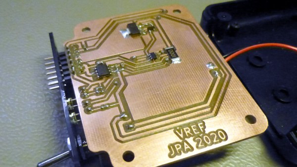
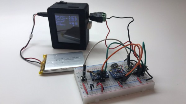
The cost of a reference source goes up with the degree of accuracy required, and can stretch into the many millions of dollars if you are seeking the standards of a national metrology institute, but fortunately [Petteri]’s requirements were considerably more modest. 0.02% accuracy would suffice. An Analog Devices precision voltage reference driving a low-offset op-amp with a driver transistor supplies current to a 0.01% precision resistor, resulting in a reference current source fit for his needs. The reference is available in a range of voltages, his chosen 2.048 volts gave a 2.048 mA current sink with a 100 ohm resistor.

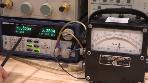
In a way it is a miracle of technology that the cheapest digital multimeter on the market can still have a surprisingly good level of calibration thanks to its on-chip bandgap voltage reference, but it never hurts to have a means to check your instruments. Some of us still rather like analogue multimeters, but beware — calibration at the cheaper end of that market can sometimes be lacking.

If You Need A Measurement Tool Just Build A Measurement Tool

[Darlan Johnson] was working on a wearable project and needed a way to measure the change in voltage and current over time. 

Most measurement tools are designed to take snapshots of a system’s state in a very small window of time, but there are few common ones designed to observe and log longer periods. It’s an interesting point, for example, many power supply related failures such as resets occur sporadically. Longer timescale measuring devices could pick these up.

[Darlan] had a ton of Feathers and shields lying around, and combined them into the needed instrument. An INA219 current sensor records the measurements. They are then displayed on a TFT and logged to an SD card. Everything is bundled into a neat 3D printed case along with a battery for wireless operation. A set of barrel connectors provide the breakout to split the wires for the current measurement.

It’s a neatly done hack and we can see it as a nice addition to any hacker’s measurement drawer.

Flux Gate Magnetometers Make A Special Current Probe

There are moments when current measurement is required on conductors that can’t be broken to insert a series resistor, nor encircled with a current transformer. These measurements require a completely non-invasive technique, and to satisfy that demand there are commercial magnetometer current probes. These probes are however not for the light of wallet, so [ensgoldmine] has created a much cheaper alternative.

The Texas Instruments GRV425 flux gate magnetometer integrated circuit on its TI evaluation module provides the  measuring element placed at the tip of a probe as close as possible to the conductor to be measured, with another GRV425 module at the head of the probe to measure ambient magnetic field for calibration purposes.  An Arduino Due measures and processes the readings, chosen due to its higher-resolution ADC than the more ubiquitous Arduino Uno.

The write-up is interesting even if you have no need for a current probe, because of its introduction to these sensing elements. Because it’s a rare first for Hackaday, we’ve never taken a close look at them before other than as an aside when talking about a scientific instrument on Mars.

Spin Me Right Round, Baby: Generator Building Experiments For Mere Mortals

How many of you plan to build a wind-powered generator in the next year? Okay, both of you can put your hands down. Even if you don’t want to wind your coils manually, learning about the principles in an electric generator might spark your interest. There is a lot of math to engineering a commercial model, but if we approach a simple version by looking at the components one at a time, it’s much easier to understand.

For this adventure, [K&J Magnetics] start by dissect a commercial generator. They picked a simple version that might serve a campsite well, so there is no transmission or blade angle apparatus to complicate things. It’s the parts you’d expect, a rotor and a stator, one with permanent magnets and the other with coils of wire.

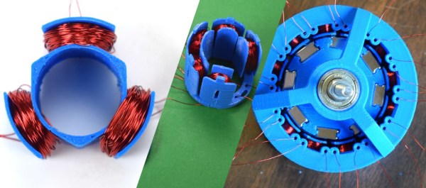
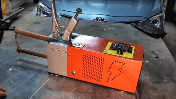
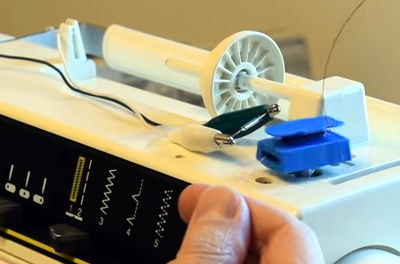
The fun of this project is copying the components found in the commercial hardware and varying the windings and coil count to see how it affects performance. If you have ever wound magnet wire around a nail to make an electromagnet, you know it is tedious work so check out their 3D printed coil holder with an embedded magnet to trigger a winding count and a socket to fit on a sewing machine bobbin winder. If you are going to make a bunch of coils, this is going to save headaches and wrist tendons.

They use an iterative process to demonstrate the effect of multiple coils on a generator. The first test run uses just three coils but doesn’t generate much power at all, even when spun by an electric drill. Six windings do better, but a dozen finally does the trick, even when turning the generator by hand. We don’t know about their use of cheap silicone diodes though, that seems like unintentional hobbling, but we digress.

Making turbine blades doesn’t have to be a sore chore either, and PVC may be the ticket there, you may also consider the vertical axis wind turbine which is safer at patio level. Now, you folks building generators, remember to tip us off!

Continue reading “Spin Me Right Round, Baby: Generator Building Experiments For Mere Mortals”

Old Wattmeter Uses Magnetics To Do The Math

Measuring power transfer through a circuit seems a simple task. Measure the current and voltage, do a little math courtesy of [Joule] and [Ohm], and you’ve got your answer. But what if you want to design an instrument that does the math automatically? And what if you had to do this strictly electromechanically?

That’s the question [Shahriar] tackles in his teardown of an old lab-grade wattmeter. The video is somewhat of a departure for him, honestly; we’re used to seeing instruments come across his bench that would punch a seven-figure hole in one’s wallet if acquired new. These wattmeters are from Weston Instruments and are beautiful examples of sturdy, mid-century industrial design, and seem to have been in service until at least 2013. The heavy bakelite cases and sturdy binding posts for current and voltage inputs make it seem like the meters could laugh off a tumble to the floor.

But as [Shahriar] discovers upon teardown of a sacrificial meter, the electromechanical movement behind the instrument is quite delicate. The wattmeter uses a moving coil meter much like any other panel meter, but replaces the permanent magnet stator with a pair of coils. The voltage binding posts are connected to the fine wire of the moving coil through a series resistance, while the current is passed through the heavier windings of the stator coils. The two magnetic fields act together, multiplying the voltage by the current, and deflect a needle against a spring preload to indicate the power. It’s quite clever, and the inner workings are a joy to behold.

We just love looking inside old electronics, and moving coil meters especially. They’re great gadgets, and fun to repurpose, too.

Continue reading “Old Wattmeter Uses Magnetics To Do The Math”

A Dramatic Demo Of AC Versus DC Switching

Switches seem to be the simplest of electrical components – just two pieces of metal that can be positioned to either touch each other or not. As such it would seem that it shouldn’t matter whether a switch is used for AC or DC. While that’s an easy and understandable assumption, it can also be a dangerous one, as this demo of AC and DC switching dramatically reveals.

Using a very simple test setup, consisting of an electric heater for a load, a variac to control the voltage, and a homemade switch, [John Ward] walks us through the details of what happens when those contacts get together. With low-voltage AC, the switch contacts exhibit very little arcing, and even with the voltage cranked up all the way, little more than a brief spark can be seen on either make or break. Then [John] built a simple DC supply with a big rectifier and a couple of capacitors to smooth things out and went through the same tests. Even at a low DC voltage, the arc across the switch contacts was dramatic, particularly upon break. With the voltage cranked up to the full 240-volts of the UK mains, [John]’s switch was essentially a miniature arc welder, with predictable results as the plastic holding the contacts melted. Don your welding helmet and check out the video below.

As dramatic as the demo is, it doesn’t mean we won’t ever be seeing DC in the home. It just means that a little extra engineering is needed to make sure that all the components are up to snuff.

Continue reading “A Dramatic Demo Of AC Versus DC Switching”

Fail Of The Week: The Spot Welder Upgrade That Wasn’t

Even when you build something really, really nice, there’s always room for improvement, right? As it turns out for this attempted upgrade to a DIY spot welder, not so much.

You’ll no doubt recall [Mark Presling]’s remarkably polished and professional spot welder build that we featured some time ago. It’s a beauty, with a lot of thought and effort put into not only the fit and finish but the function as well. Still, [Mark] was not satisfied; he felt that the welder was a little underpowered, and the rewound microwave oven transformer was too noisy. Taking inspiration from an old industrial spot welder, he decided to rebuild the transformer by swapping the double loop of battery cable typically used as a secondary with a single loop of thick copper stock. Lacking the proper sized bar, though, he laminated multiple thin copper sheets together before forming the loop. On paper, the new secondary’s higher cross-sectional area should carry more current, but in practice, he saw no difference in the weld current or his results. It wasn’t all bad news, though — the welder is nearly silent now, and the replaced secondary windings were probably a safety issue anyway, since the cable insulation had started to melt.

Given [Mark]’s obvious attention to detail, we have no doubt he’ll be tackling this again, and that he’ll eventually solve the problem. What suggestions would you make? Where did the upgrade go wrong? Was it the use of a laminated secondary rather than solid bar stock? Or perhaps this is the best this MOT can do? Sound off in the comments section.

Continue reading “Fail Of The Week: The Spot Welder Upgrade That Wasn’t”