The Simplest Curve Tracer Ever

To a lot of us, curve tracing seems to be one of those black magic things that only the true wizards understand. But as [DiodeGoneWild] explains, curve tracing really isn’t all that complicated, and it doesn’t even require specialized test instruments — just a transformer, a couple of resistors, and pretty much whatever oscilloscope you can lay your hands on.

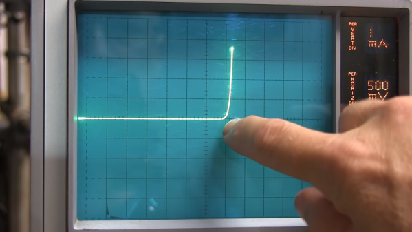
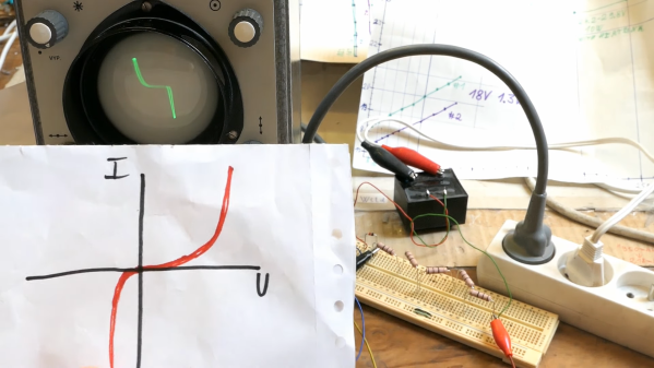
True to his handle, [DiodeGoneWild] concentrates on the current-voltage curves of Zener diodes in the video below, mainly as a follow-up to his recent simple linear power supply project, where he took a careful look at thermal drift to select the best Zener for the job. His curve tracer is super simple — just the device under test in series with a bunch of 10-ohm resistors and the secondary winding of a 12-volt transformer. The probes of his oscilloscope — a no-frills analog model — go across the DUT and the resistor, and with the scope in X-Y mode, the familiar current-voltage curve appears. Sure, the trace is reversed, but it still provides a good visualization of what’s going on. The technique also works on digital scopes; just be ready for a lot of twiddling to get into X-Y mode and to get the trace aligned.

Of course it’s not just diodes that can be tested with a curve tracer, and [DiodeGoneWild] showed a bunch of other two-lead components on his setup. But for our money, the neatest trick here was using a shorted bridge rectifier to generate a bright spot on the curve to mark the zero crossing point. Clever indeed, and pretty useful on a scope with no graticule.

Continue reading “The Simplest Curve Tracer Ever”

Hack Your Heathkit To Trace MOSFET Curves

[TRX Lab] has an old Heathkit model IT-1121 curve tracer, and wants to modify it so he can plot the I-V curves of MOSFETs. For the uninitiated, curve tracers are used to determine the precise characteristics of components by measuring the output for a set of specific inputs – either voltage or current depending on the device you’re testing.

The IT-1121 was introduced in 1973 and supports bipolar and FET transistors of types NPN, PNP, N-channel, and P-channel, along with various other semiconductor devices. But [TRX] wanted to enhance the tester to deal with MOSFETs as well.

The IT-1121 is very flexible, and has selector switches for all the usual polarity and sweep settings — Heathkit also sold a model IT-3121 in later years, but this seems to have been the same basic tester. [TRX] found two shortcomings when plotting the I-V curve of MOSFETs. First, there is no way to apply a Vgs threshold voltage to the curves. Second, when set for FET testing, the polarity of the gate voltage stair step waveform doesn’t match the desired polarity of the drain-source voltage.

In the video below the break, [TRX] first walks us through some of the reasons you’d want a curve tracer in your lab. In the next part of the video, he breadboards up the modification for testing, and finally buttons it up and installs it. Implementing the modification was pretty straightforward. [TRX] designed four op-amp circuit that adds the adjustable offset and a switch to toggle the polarity of the gate voltage waveform. The whole thing fits on a small breadboard inside the case. Two holes are drilled in the panel for the potentiometer and switch.

There’s no GitHub repository for this project, but he presents the full details in the video and says viewers are free to make snapshots of the schematics and layout if they want to build their own.

Modern I-V curve tracers are pretty pricey. Even used, decades-old professional curve tracers are above the budget of most home and small office labs. If you have, or can get one of these at a decent price, this would be a modification well worth considering. You might also consider a home-brew tracer, like this one we covered last year.

Continue reading “Hack Your Heathkit To Trace MOSFET Curves”

Curve Tracer Design For Power Vacuum Tubes Testing

Regardless of the mythical qualities that are all too often attributed to vacuum tubes, they are still components that can be damaged and wear out over time. Much like with transistors and kin, they come with a stack of datasheets, containing various curves detailing their properties and performance. These curves will change as a part ages, and validating these curves can help with debugging a vacuum tube-based circuit. This is where one can either spend an enormous sum on a commercial curve tracer like the Tektronix 570, or build your own, as [Basin Street Design] has done.

A semi-retired electronics design engineer by trade, he has previously covered the development of the curve tracer on Instructables for the version 1 and version 1.1. What this device essentially allows you to do is sweep the connected tube through its input parameter ranges, while observing the resulting curves on an attached (external) oscilloscope. Here a storage oscilloscope (or DSO) is immensely helpful to capture the curves.

In the project pages, the in-depth theory and functioning of the circuitry is explained, along with the schematics and a number of builds. The project has been around since before the VBA tracer which we covered last year, both of which are infinitely more affordable than a genuine Tektronix 570.

Thanks to [Fernando] for the tip.

Homebrew Curve Tracer Competes With The Big Guns

When we first saw the VBA curve tracer, we thought it might have something to do with Visual Basic for Applications. But it turns out it is a mash up of the names of the creators: [Paul Versteeg], [Bud Bennett], and [Mark Allie]. [Paul] designed an original prototype back in 2017. Since then, the project has grown and lessons were learned. The final curve tracer is pretty impressive in more ways than one.

If you’ve never used a curve tracer, they allow you to characterize components using their characteristic curve of voltage versus current. You use an oscilloscope as an output device. This instrument is often used by engineers trying to understand or match devices like diodes, transistors, or — in some cases — even tubes. So if you want to measure the collector-emitter breakdown voltage, for example, or the collector cutoff current, this is your go-to device. You can also match gains in circuits where that matters (for example, a push-pull circuit where two transistors amplify different parts of the same signal).

If you want to understand more about how it works, there are a series of blog posts covering the evolution of the device. You can also find the design files on GitHub. There is also a handy post showing many types of measurements you might want to make.

This is a good-looking project. We’ve seen it done on the cheap, but slowly. Or spend $15 and do better. We doubt any of these have high enough voltages to do most tubes, but they made the same basic instrument for tubes back in the 1950s.

Rodriguez — IV Curve Tracer On The Cheap

In response to an online discussion on the Electrical Engineering Stack Exchange, [Joseph Eoff] decided to prove his point by slapping together a bare-bones IV curve tracer using an Arduino Nano and a handful of passives. But he continued to tinker with the circuit, seeing just how much improvement was possible out of this simple setup. He squeezes a bit of extra resolution out of the PWM DAC circuit by using the Timer1 library to obtain 1024 instead of 256 steps. For reading voltages, he implements oversampling (and in some cases oversampling again) to eke out a few extra bits of resolution from the 10-bit ADC of the Nano. The whole thing is controlled by a Python / Qt script to generate the desired plots.

While it works and gives him the IV curves, this simplicity comes at a price. It’s slow — [Joseph] reports that it takes several minutes to trace out five different values of base current on a transistor. It was this lack of speed that inspired him to name the project after cartoon character Speedy Gonzales’s cousin,  Slowpoke Rodriguez, AKA “the slowest mouse in all of Mexico”. In addition to being painstakingly slow, the tracer is limited to 5 volts and currents under 5 milliamps.

[Joseph] documents the whole design and build process over on his blog, and has made the source code available on GitHub should you want to try this yourself. We covered another interesting IV curve tracer build on cardboard ten years ago, but that one is much bigger than the Rodriguez.

Tubes Have Character With A Tek 570

When tubes were king, you could go to a drugstore with a box full of them from your TV. There would be a tester that would tell you what tubes were bad and, of course, you could buy the replacements for them. That kind of tube tester was pretty simple. If you wanted to really know how to design with a tube or test its parameters, you were much better off with a curve tracer like the Tektronix 570 that [tomtektest] shows off in two recent videos that you can see below.

That piece of kit fell into [Tom’s] lap thanks to an observant delivery driver. The 1955 instrument is very similar to a semiconductor curve tracer but, of course, has the ability to provide much higher voltage for the tubes. The basic idea is that the X axis sweeps from a few volts up to 100s of volts. The vertical scale will show the plate, screen, or grid current. From those curves you can learn a lot about the characteristics of the tube.

Continue reading “Tubes Have Character With A Tek 570”

Diode Basics By [W2AEW]

We didn’t think we needed a basic guide to diodes until we saw it was from [W2AEW], and then we knew we’d pick up some new things. Entitled “Diodes from Ideal to Real” the 18-minute video doesn’t disappoint with a mix of notes and time with a curve tracer to learn all about these devices.

As is typical for a [W2AEW] video this doesn’t just cover the simple operation of diode. It includes topics such as dynamic resistance, junction capacitance, and talks about a wide variety of diode types.

Continue reading “Diode Basics By [W2AEW]”