Laptop computers may be ubiquitous today, but there was a time when they were the exclusive preserve of rich businesspeople. Back in the early ’90s, the significant added cost of portability was something that few were willing to pay. As a result, not many laptops from those days survive; for those that do, keeping them running can be quite a challenge due to their compact construction and use of non-standard components.
[Adalbert] ran into these problems when he got his hands on a Toshiba T3200SXC from 1991. As the first laptop ever to feature a color TFT display, it’s very much worth preserving as an historical artifact. Sadly, the original display was no longer working: it only displayed a very faint image and went completely blank soon after. Leaky capacitors then destroyed the power supply board, leaving the laptop completely dead. [Adalbert] then began to ponder his options, which ranged from trying to repair the original components to ripping everything out and turning this into a modern-computer-in-an-old-case project.
In the end he went for an option in between, which we as preservationists can only applaud: he replaced the display with a modern one of the correct size and resolution and built a new custom power supply, keeping the rest of the computer intact as far as possible. [Adalbert] describes the overall process in the video embedded below and goes into lots of detail on his hackaday.io page.
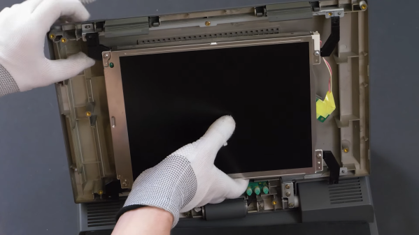
Connecting a modern LCD screen was not as difficult as it might seem: where the old display had an RGB TTL interface with three bits per color, the new one had a very similar system with six bits per color. [Adalbert] made an adapter PCB that simply connected the three bits from the laptop to the highest three bits on the screen. A set of 3D-printed brackets ensured a secure fit of the new screen in the classic case.
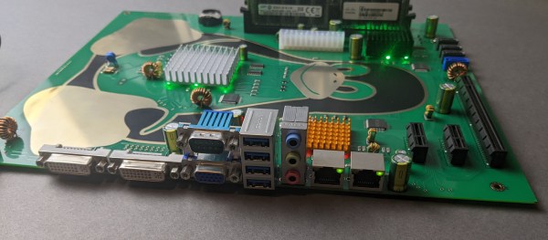
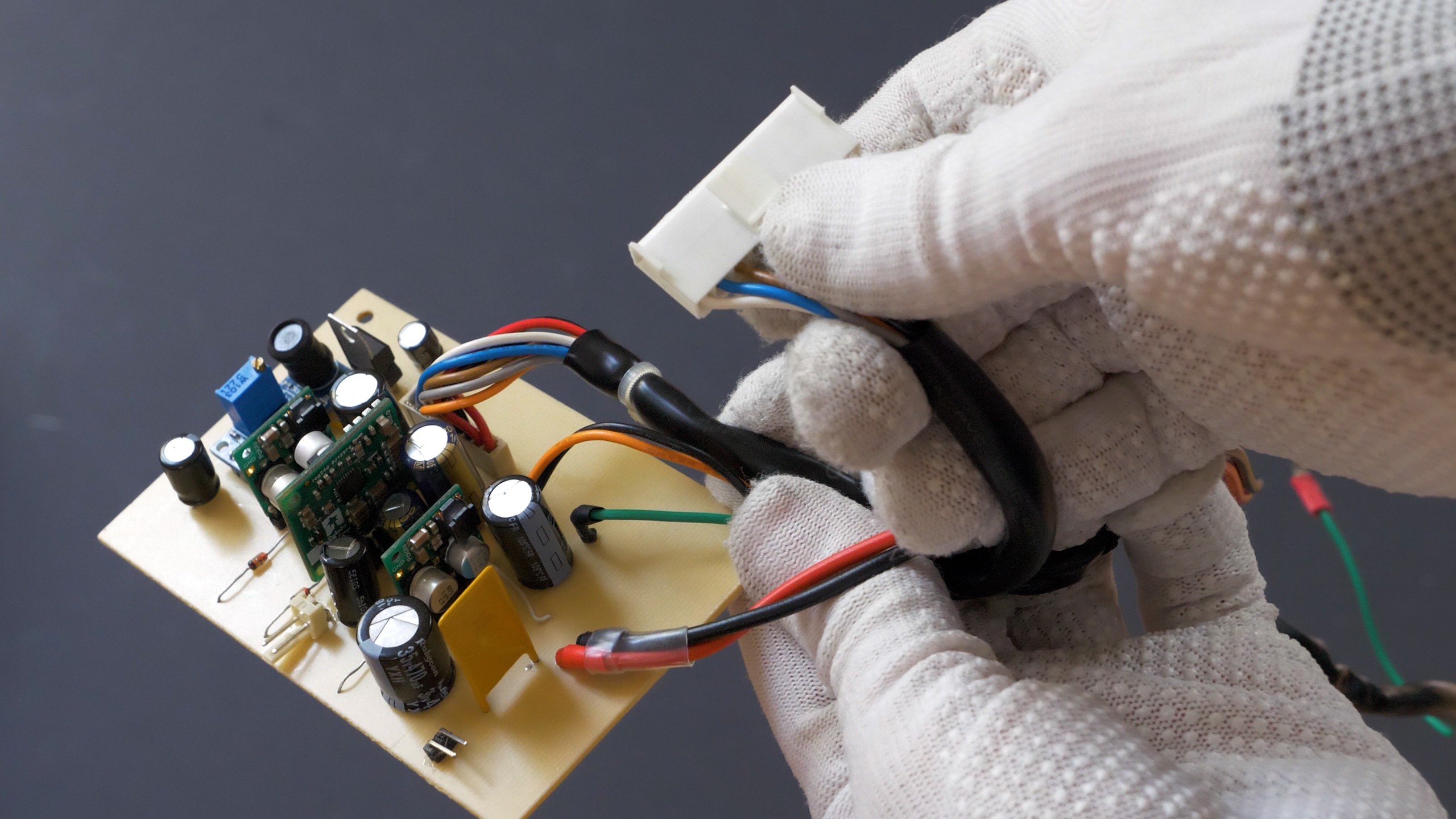
 For the power supply [Adalbert] took a similar approach. He designed a PCB with several DC/DC converters that fit easily inside the computer’s case, leaving enough space to add a battery. This made the old Toshiba more portable than it ever was — believe it or not, the original T3200SXC could only be used with a mains connection.
Once the laptop was restored to working order, [Adalbert] added a few finishing touches: a sound card and speakers made it suitable as a gaming platform, and a network card gave it rudimentary online capabilities. The end result is a T3200SXC that looks and feels exactly the way it did when it was new, but with a few added features. That’s a really satisfying result: many classic laptop projects add modern computing hardware, or even completely replace the original contents. You might also want to check out [Adalbert]’s unusual 3D printer based PCB manufacturing technique that he used for the new power supply.
Continue reading “Hackaday Prize 2022: Repairing A Vintage Laptop With Modern Components” →

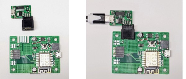
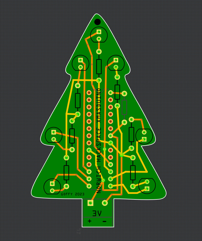 The brains of this festive little tree is an ATmega328P, which you probably recognize as the microcontroller that powers the Arduino Uno. Although this circuit has none of the extra bits you’d find on an Uno, not even a crystal oscillator, it can still be programmed with Arduino and use the 8 MHz internal clock.
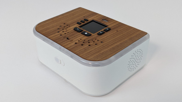
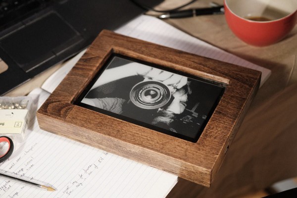
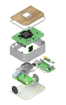 concerns of privacy and data security; they look less and less attractive the closer you look. Luckily the Raspberry Pi and its friends have improved the accessibility to the point where it’s positively easy to create whatever you want with whatever hardware you need, and to that end we think [Mehrdad] has done a splendid job.