Error Detection And Correction: Reed-Solomon, Convolution And Trellis Diagrams

Transferring data without error when there is a lot of background noise is a challenge. Dr. Claude E. Shannon in 1948 provided guidance with his theory addressing the capacity of a communications channel in the presence of noise. His work quickly spread beyond communications into other fields. Even other aspects of computer use were impacted. An example is the transfer of data from a storage medium, like a hard drive or CD-ROM. These media and their sensors are not 100% reliable so errors occur. Just as Shannon’s work defines communication channel capacity it defines the transfer rate from a media surface to the read head.

Shannon told us how much could be passed through a channel but didn’t say how. Since 1948 a lot of research effort went into accurately detecting errors and correcting them. Error correction codes (ECC) add extra bits to messages, but their cost pays off in their ability to work around errors. For instance, without ECC the two Voyager spacecraft, now leaving our solar system, would be unable to phone home with the information they’ve gathered because noise would overwhelm their signals. Typically in hardware, like memory, error correction is referred to as ECC. In communications, the term forward error correction (FEC) is used.

Robust communication, or data transfer, is a combination of fancy software and tricky signal processing. I’m going to focus on the software side in this article. You may find some of these techniques useful in communicating data among your devices. While I’ll be using the term communications keep in mind this is applicable to transferring data in general.

Continue reading “Error Detection And Correction: Reed-Solomon, Convolution And Trellis Diagrams”

Grandma’s Phone, DSL, And The Copper They Share

My DSL line downloads at 6 megabits per second. I just ran the test. This is over a pair of copper twisted wires, the same Plain Old Telephone Service (POTS) twisted pair that connected your Grandmother’s phone to the rest of the world. In fact, if you had that phone you could connect and use it today.

18zbmki8n3xgkjpg
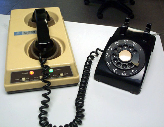
I can remember the old 110 bps acoustic coupler modems. Maybe some of you can also. Do you remember upgrading to 300 bps? Wow! Triple the speed. Gradually the speed increased through 1200 to 2400, and then finally, 56.6k. All over the same  of wires. Now we feel short changed if were not getting multiple megabits from DSL over that same POTS line. How can we get such speeds over a system that still allows your grandmother’s phone to be connected and dialed? How did the engineers know these increased speeds were possible?

shannon_maze_hr
Claude Shannon with his maze running mechanical mouse

The answer lies back in 1948 with Dr. Claude Shannon who wrote a seminal paper, “A Mathematical Theory of Communication”. In that paper he laid the groundwork for Information Theory. Shannon also is recognized for applying Boolean algebra, developed by George Boole, to electrical circuits. Shannon recognized that switches, at that time, and today’s logic circuits followed the rules of Boolean Algebra. This was his Master’s Thesis written in 1937.

Shannon’s Theory of Communications explains how much information you can send through a communications channel at a specified error rate. In summary, the theory says:

  • There is a maximum channel capacity, C,
  • If the rate of transmission, R, is less than C, information can be transferred at a selected small error probability using smart coding techniques,
  • The coding techniques require intelligent encoding techniques with longer blocks of signal data.

What the theory doesn’t provide is information on the smart coding techniques. The theory says you can do it, but not how.

In this article I’m going to describe this work without getting into the mathematics of the derivations. In another article I’ll discuss some of the smart coding techniques used to approach channel capacity. If you can understand the mathematics, here is the first part of the paper as published in the Bell System Technical Journal in July 1948 and the remainder published later that year. To walk though the system used to fit so much information on a twisted copper pair, keep reading.

Continue reading “Grandma’s Phone, DSL, And The Copper They Share”

Build An In Line Network Bandwidth Monitor

[Kurt] likes to know what’s going on with his network. He already uses bandwidth checking software on his DD-WRT capable router, but he wanted a second opinion. So he built his own network monitor. [Kurt] started by building a passive Ethernet tap. He then needed a network interface chip that would serve his purposes. The common Wiznet chips used with Arduinos didn’t allow enough manipulation of raw packet data, so he switched to a Microchip ENC624J600 (PDF). The Microchip controller allowed him to count the bytes in the raw Ethernet packets.

With the Ethernet interface complete, [Kurt] turned his attention to a microcontroller to run the show. He started with an Arduino, but the lack of debugging quickly sent him to an Atmega128 in Atmel Studio. After getting the basic circuit working, [Kurt] switched over to a PIC24F chip. With data finally coming out of the circuit, he was able to tell that his original back-of-the-napkin calculations for bandwidth were wrong. [Kurt] created a PCB to hold the microcontroller, then wrote a Python program to plot the data output from his circuit. The bandwidth plot matched up well with the plot from DD-WRT. Now he just needs a giant LED matrix to show off his current network stats!

Learn Wireless Sensor Networks With Nanode

wicked

Getting a device on the internet is great – but what if you want to monitor multiple wireless sensors? The [WickedDevice] crew have been publishing a tutorial series focusing on just that. Their weapon of choice is the Nanode, an Arduino based wireless sensor system we’ve seen a few times in the past. So far the first and second parts have been posted up. Part one starts with an explanation of the Arduino and Nanode platform, and takes us through connecting the Nanode to a wireless temperature sensor. Part two walks through the hardware and code changes to add multiple wireless sensors to the system. Part three will focus on getting the entire network up on the internet, and piping data onto the Xively data hosting site.

This tutorial does begin a bit on the basic side, covering the installation of the Arduino software environment. This may seem a bit simplistic for some of our readers, but we think this type of tutorial is necessary. It helps ‘newbies’ get started down what could otherwise be a difficult path. For more advanced readers, it’s easier to skip past steps you already know than it is to try to hunt down information that isn’t there.