Remote-Controlled Hypercar Slices Through Air

Almost all entry-level physics courses, and even some well into a degree program, will have the student make some assumptions in order to avoid some complex topics later on. Most commonly this is something to the effect of “ignore the effects of wind resistance” which can make an otherwise simple question in math several orders of magnitude more difficult. At some point, though, wind resistance can’t be ignored any more like when building this remote-controlled car designed for extremely high speeds.

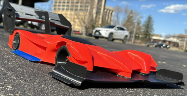
[Indeterminate Design] has been working on this project for a while now, and it’s quite a bit beyond the design of most other RC cars we’ve seen before. The design took into account extreme aerodynamics to help the car generate not only the downforce needed to keep the tires in contact with the ground, but to keep the car stable in high-speed turns thanks to its custom 3D printed body. There is a suite of high-speed sensors on board as well which help control the vehicle including four-wheel independent torque vectoring, allowing for precise control of each wheel. During initial tests the car has demonstrated its ability to  corner at 2.6 lateral G, a 250% increase in corning speed over the same car without the aid of aerodynamics.

We’ve linked the playlist to the entire build log above, but be sure to take a look at the video linked after the break which goes into detail about the car’s aerodynamic design specifically. [Indeterminate Design] notes that it’s still very early in the car’s development, but has already exceeded the original expectations for the build. There are also some scaled-up vehicles capable of transporting people which have gone to extremes in aerodynamic design to take a look at as well.

Continue reading “Remote-Controlled Hypercar Slices Through Air”

Share Your Projects: Making Helpful PCBs

When it comes to things that hackers build, PCBs are a sizeable portion of our creative output. It’s no wonder – PCB design is a powerful way to participate in the hardware world, making your ideas all that more tangible with help of a friendly PCB fab. It’s often even more lovely when the PCB has been designed for you, and all you have to do is press “send” – bonus points if you can make a few changes for your own liking!

A lot of the time, our projects are untrodden ground, however, and a new design needs to be born. We pick out connectors, work through mechanical dimensions, figure out a schematic and check it with others, get the layout done, and look at it a few more times before sending it out for production. For a basic PCB, that is enough – but of course, it’s no fun to stop at ‘basic’, when there’s so many things you can do at hardly any cost.

Let’s step back a bit – you’ve just designed a board, and it’s great! It has all the chips and the connectors you could need, and theoretically, it’s even supposed to work first try. Now, let’s be fair, there’s an undeniable tendency – the more PCBs you design, the better each next one turns out, and you learn to spend less time on each board too. As someone with over two hundred PCBs under her belt, I’d like to show you a bunch of shortcuts that make your PCB more helpful, to yourself and others.

There’s a few ways that you can share your PCB projects in a more powerful way – I’d like to point out a few low-hanging fruits, whether README.md files or markings on the PCB itself. I’ve been experimenting quite a bit with external and embedded documentation of PCBs, as well as PCB sharing methods, got some fun results, and I’d like to share my toolkit through a few punchy examples and simple tricks. I’d also like to hear about yours – let’s chat! Continue reading “Share Your Projects: Making Helpful PCBs”

How To Model A Twisted Part In FreeCAD

Quick references are handy, but sometimes it’s nice to have a process demonstrated from beginning to end. In that spirit, [Darren Stone] created a video demonstrating how to model a twisted part in FreeCAD, showing the entire workflow of creating the part as a blend of surfaces and curves that get turned into a solid.

FreeCAD is organized using the concept of multiple “workbenches” which are each optimized for different tools and operations, and [Darren] walks through doing the same jobs in a few different ways.

This twisted bracket is a simple part that is nevertheless nontrivial from a CAD perspective, and that makes it a good candidate for showing off the different workbenches and tools.

The video below is also pretty good overall demonstration of what designing a part from a mechanical drawing looks like when done in FreeCAD. As for mechanical drawings themselves, we’ve seen FreeCAD can be used to make those, too.

Continue reading “How To Model A Twisted Part In FreeCAD”

Hinges Live Inside 3D Prints

Since desktop 3D printers have become more common, we’ve seen dramatic shifts in all kinds of areas such as rapid prototyping, antique restoration, mass production of consumer goods, or even household repairs that might not have been possible otherwise. There are a lot of unique manufacturing methods that can be explored in depth with a 3D printer as well, and [Slant 3D] demonstrates how one such method known as the living hinge can be created with this revolutionary new tool.

Living hinges, unlike a metal hinge you might pick up at a hardware store, are integrated into the design of the part and made of the same material. Typically found in plastic containers, they allow for flexibility while keeping parts count and cost low. The major downside is that they create stresses in the materials when used, so their lifespan is finite. But there are a number of ways to extend their life, albeit with a few trade-offs.

The first note is to make sure that you’re using the right kind of plastic, but after that’s taken care of [Slant 3D] builds a few flexible parts starting with longer circular-shaped living hinge which allows greater range of motion and distributes the forces across a wider area, at a cost of greater used space and increased complexity. A few other types of living hinges are shown to use less space in some areas, but make the hinges only suitable for use in other narrower applications.

One of the more interesting living hinges he demonstrates is one that’s more commonly seen in woodworking, known there as a kerf bend. By removing strips of material from a sheet, the entire sheet can be rotated around the cuts. In woodworking this is often done by subtracting material with a CNC machine or a laser cutter, but in 3D printing the voids can simply be designed into the part.

Continue reading “Hinges Live Inside 3D Prints”

The BSides: More Curious Uses Of Off-the-shelf Parts

Off-the-shelf stock parts are the blocks from which we build mechanical projects. And while plenty of parts have dedicated uses, I enjoy reusing them in ways that challenge what they were originally meant for while respecting the constraints of their construction. Building off of my piece from last time, I’d like to add to your mechanical hacking palette with four more ways we can re-use some familiar off-the-shelf parts. Continue reading “The BSides: More Curious Uses Of Off-the-shelf Parts”

It’s Opposite Day For This Novel Wankel Engine

The Wankel engine seems to pop up in surprising places every so often, only to disappear into the ether before someone ultimately resurrects it for a new application and swears to get it right this time. Ultimately they come across the same problems that other Wankels suffered from, namely poor fuel efficiency and issues with reliability. They do have a surprising power-to-weight ratio and a low parts count, though, which is why people keep returning to this well, although this time it seems like most of the problems might have been solved simply by turning the entire design inside out.

A traditional Wankel engine has a triangular-shaped rotor that rotates around a central shaft inside an oval-shaped housing. This creates three chambers which continually revolve around inside the engine as the rotor spins. The seals that separate the chambers are notoriously difficult to lubricate and maintain. Instead of using a rotor inside of a chamber, this design called the X-Engine essentially uses a chamber inside of a rotor, meaning that the combustion chamber and the seals stay in fixed locations instead of spinning around. This allows for much better lubrication of the engine and also much higher efficiency. By flipping the design on its head it is able to maintain a low moving parts count, high compression ratio, and small power-to-weight ratio all while improving reliability and performance and adding the ability to directly inject fuel rather than rely on carburetion or other less-ideal methods of fuel delivery that other Wankels require.

Astute internal combustion aficionados will note that this engine is still of a two-stroke design, and thus not likely to fully eliminate the emissions problems with Wankels in a way that is satisfactory to regulators of passenger vehicles. Instead, the company is focusing on military, commercial, and aerospace applications where weight is a key driver of design. We’ve seen time and time again how the Wankel fails to live up to its promises though, and we hope that finally someone has cracked the code on one that solves its key issues.

Opening Up ASIC Design

The odds are that if you’ve heard about application-specific integrated circuits (ASICs) at all, it’s in the context of cryptocurrency mining. For some currencies, the only way to efficiently mine them anymore is to build computers so single-purposed they can’t do anything else. But an ASIC is a handy tool to develop for plenty of embedded applications where efficiency is a key design goal. Building integrated circuits isn’t particularly straightforward or open, though, so you’ll need some tools to develop them such as OpenRAM.

Designing the working memory of a purpose-built computing system is a surprisingly complex task which OpenRAM seeks to demystify a bit. Built in Python, it can help a designer handle routing models, power modeling, timing, and plenty of other considerations when building static RAM modules within integrated circuits. Other tools for taking care of this step of IC design are proprietary, so this is one step on the way to a completely open toolchain that anyone can use to start building their own ASIC.

This tool is relatively new and while we mentioned it briefly in an article back in February, it’s worth taking a look at for anyone who needs more than something like an FPGA might offer and who also wants to use an open-source tool. Be sure to take a look at the project’s GitHub page for more detailed information as well. There are open-source toolchains if you plan on sticking with your FPGA of choice, though.