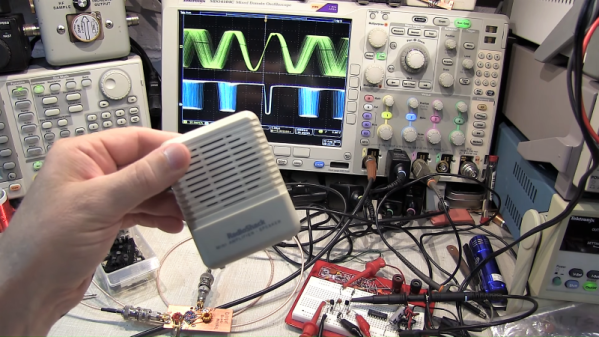
An “Infinite Impedance Detector” might sound a little like something that [Zaphod Beeblebrox] would use to zip around the galaxy. It’s not, of course, but it is an interesting and useful demodulator for AM radio signals, as [Sebastian Westerhold] over at Baltic Labs explains in the brief but well-done video below.
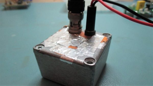
If you’ve ever browsed through schematics of old vacuum tube radios, [Sebastian]’s JFET-based detector circuit might look strangely familiar. That’s because this demodulator is about as close to a direct translation between a vacuum tube circuit and a silicon circuit as possible. In fact, [Sebastian] even used literature from the triode version of this detector to figure out the values for some of the components. The only active component is a BF256B JFET; the rest are a small handful of resistors and caps. Construction is in the ever-popular ugly style.
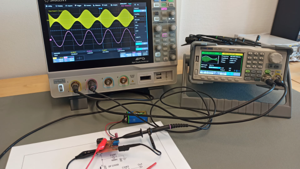
The test setup is simple — a function generator set to 455 kHz and modulated with a 1,000 Hz sine wave. The detector demodulates the audio signal very cleanly, judging by the oscilloscope traces. Just for fun, [Sebastian] also tried a 10.7 MHz carrier with a 1,500 Hz audio modulation, and that worked fine too. He also tried a variation on the circuit with an IF transformer on the input. That circuit works just about the same as the transformerless version, although it does provide a little gain.
Earth-shattering stuff? Probably not. But it does show the fun you can have with a scrap of PCB and a few components, and seems like it could easily be the kind of project that would take you down the RF rabbit hole. Thanks to [Sebastian] for sharing this one with us.
Most crystal radio receivers have a decidedly “field expedient” look to them. Fashioned as they often are from a few turns of wire around an oatmeal container and a safety pin scratching the surface of a razor blade, the whole assembly often does a great impersonation of a pile of trash whose appearance gives little hope of actually working. And yet work they do, usually, pulling radio signals out of thin air as if by magic.
Not all crystal sets take this slapdash approach, of course, and some, like this homebrew multiband crystal receiver, aim for a feature set and fit and finish that goes way beyond the norm. The “Husky” crystal set, as it’s called by its creator [alvenh], looks like it fell through a time warp right from the 1920s. The electronics are based on the Australian “Mystery Set” circuit, with modifications to make the receiver tunable over multiple bands. Rather than the traditional galena crystal and cat’s whisker detector, a pair of1N34A germanium diodes are used as rectifiers — one for demodulating the audio signal, and the other to drive a microammeter to indicate signal strength. A cat’s whisker is included for looks, though, mounted to the black acrylic front panel along with nice chunky knobs and homebrew rotary switches for band selection and antenna.
As nice as the details on the electronics are, it’s the case that really sells this build. Using quarter-sawn oak salvaged from old floorboards. The joinery is beautiful and the hardware is period correct; we especially appreciate the work that went into transforming a common flat washer into a nickel-plated escutcheon for the lock — because every radio needs a lock.
Congratulations to [Alvenh] for pulling off such a wonderful build, and really celebrating the craftsmanship of the early days of radio. Need some crystal radio theory before tackling your build? Check out [Greg Charvat]’s crystal radio deep dive.
Analyzing and troubleshooting a modern AM/FM radio, digital radio, or TV can be a pretty daunting task. However, a common AM radio is easy to understand, experiment with, and repair. Learning about that will help you understand more complex circuits later. That’s the idea behind the Elenco AM radio which is built on a wide-open PCB with markings for all the important sections. [The Offset Volt] uses one of these to explain how a receiver works, especially how a diode detects the signal and how the automatic gain control works.
Between a series of diagrams and live scope demonstrations, you can see the effects of capacitance in the receiver along with other circuit effects.
Compared to the simple diode needed to demodulate AM radio signals, the detector circuits used for FM are slightly more complicated. Wrapping your head around phase detectors, ratio detectors, discriminators, and quadrature detectors can be quite an exercise. There’s another demodulation method that’s not so common, but thankfully it’s also pretty easy to understand: the pulse counting detector.
As [Allan (W2AEW)] notes in the video below, pulse counting is a bit of a misnomer. Pulse counting works by generating a narrow, fixed-width square wave pulse at a set point in the received FM signal’s waveform, usually at the zero-crossing point. Since the frequency of the modulated carrier changes, the duty cycle of the resulting pulse train varies. That means there will be a fixed number of pulses, but by taking the average voltage of the pulse train, we can tease out the original audio frequency signal.
Simple in theory is often more complicated in practice, and [W2AEW] goes into some detail about those complications, such as needing to use a down-converter to make the peak-to-peak frequency deviation in the pulse train more easily detectable. As is his style, he walks us through a test circuit to prove that the theory works in practice. A simple two-transistor circuit generates the pulses at the zero-crossing point, a low-pass filter cleans up the signal, and a cheap audio amplifier reproduces the original audio. It’s a crude circuit to be sure, relying on the stray capacitance of the breadboard to work, but it proves the point and serves as a jumping-off point for further experiments – perhaps using an Arduino to count the pulses?
We always enjoy [W2AEW]’s videos and learn a lot from them. Not long ago we featured another of his videos talking about the mysteries of RF modulation; SSB, anyone?
If you’ve been around long enough, you’ll know there’s a long history of advances in materials science that get blown far out of proportion by both the technical and the popular media. Most of the recent ones seem to center on the chemistry of carbon, particularly graphene and nanotubes. Head back a little in time and superconductors were all the rage, and before that it was advanced ceramics, semiconductors, and synthetic diamonds. There’s always some new miracle material to be breathlessly and endlessly reported on by the media, with hopeful tales of how one or the other will be our salvation from <insert catastrophe du jour here>.
While there’s no denying that each of these materials has led to huge advancements in science, industry, and the quality of life for billions, the development cycle from lab to commercialization is generally a tad slower than the press would have one believe. And so when a new material starts to gain traction in the headlines, as perovskites have recently, we feel like it’s a good opportunity to take a close look, to try to smooth out the ups and downs of the hype curve and manage expectations.
When the topic is radiation detection, thoughts turn naturally to the venerable Geiger-Müller tube. It’s been around for ages, Russian surplus tubes are available for next to nothing, and it’s easy to use. But as a vacuum tube it can be somewhat delicate, and the high voltages needed to run it can be a little on the risky side.
Luckily, there are other ways to see what’s going on in the radioactive world, like this semiconductor radiation detector. [Robert Gawron] built it as a proof-of-concept after having built a few G-M tube detectors before. His solid-state design relies on a reverse-biased photodiode conducting when ionizing radiation hits the P-N junction. The tiny signal is amplified by a pair of low-noise op-amps and output to a BNC connector. The sensor’s analog output is sent to an oscilloscope whose trigger out is connected to a Nucleo board for data acquisition. The Nucleo is in turn connected to a Raspberry Pi for totalizing and logging. It’s a complicated chain, but the sensor appears to work, even detecting alpha emissions from thoriated TIG electrodes, a feat we haven’t been able to replicate with our G-M tube counter.
We all know CERN as that cool place where physicists play with massive, superconducting rings to smash atoms and subatomic particles to uncover secrets of matter in the Universe. To achieve this aim, they need to do a ton of research in other areas, such as development of special particle detectors.
While such developments are essential to the core research needs of the Centre, they also lead to spinoff applications for the benefit of society at large. One such outcome has been the Medipix Collaborations – a family of read-out chips for particle imaging and detection that can count single photons, allowing X-rays and gamma rays to be converted to electrical signals. It may not be possible for us hackers to get our hands on these esoteric sensors, but these devices are pretty interesting and deserve a closer look. Medipix sensors work like a camera, detecting and counting each individual particle hitting the pixels when its electronic shutter is open. This enables high-resolution, high-contrast, noise hit free images – making it unique for imaging applications.
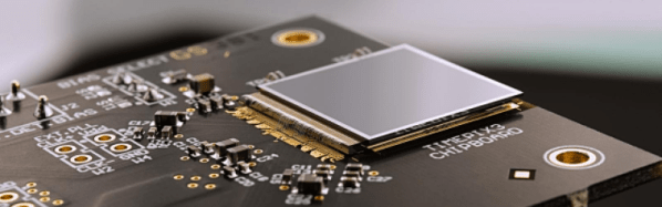
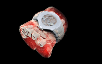
Some months back, CERN announced the first 3D color X-ray of a human made possible using the Medipix devices. The result is a high-resolution, 3D, color image of not just living structures like bones, muscular tissues and vessels, but metal objects too like the wrist watch, seen in the accompanying photograph. The Medipix sensors have been in development since the 1990’s and are presently in their 4th “generation”. Each chip consists of a top semiconducting sensor array, made from gallium arsenide or cadmium telluride. The charge collected by each pixel is transported to the CMOS ASIC electronics via “bump bonds”. The integration is vertical, with each sensing pixel connected via the bump bond to an analog section followed by a digital processing layer. Earlier versions were limited, by technology, in their tiling ability for creating larger matrices of multiple sensors. They could be abutted on three sides only, with the fourth being used for on-chip peripheral logic and wire-bond pads that permit electronic read-out. The latest Medipix4 Collaboration, still under some development, eliminates this short coming. Through-silicon-via (TSV) technology provides the possibility of reading the chips through copper-filled holes that bring the signals from the front side of the chip to its rear. All communication with the pixel matrix flows through the rear of the chip – the peripheral logic and control elements are integrated inside the pixel matrix.
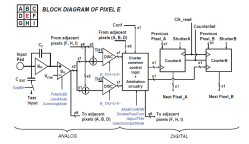
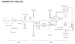
The Analog front end consists of a pre-amplifier followed by a window discriminator which has upper and lower threshold levels. The discriminator has four bits for threshold adjustment as well as polarity sensing. This allows the capture window to be precisely set. The rest of the digital electronics – multiplexers, shift registers, shutter and logic control – helps extract the data.
Further development of the Medipix (Tech Brief, PDF) devices led to a separate version called Timepix (Tech Brief, PDF). These new devices, besides being able to count photons, are capable of two additional modes. The first mode records “Time-Over-Threshold”, providing rough analog information about the energy of the photon. It does this by counting clock pulses for the duration when the signal stays above the discrimination levels. The other mode, “Time of Arrival”, measures arrival time of the first particle to impinge on the pixel. The counters record time between a trigger and detection of radiation quanta with energy above the discrimination level, allowing time-of-flight applications in imaging.
Medipix3 pixel schematic
Timepix2 pixel schematic
Besides medical imaging, the devices have applications in space, material analysis, education and of course, high energy physics. Hopefully, in a few years, hackers will lay their hands on these interesting devices and we can get to know them better. At the moment, the Medipix website has some more details and data sheets if you would like to dig deeper. For an overview on the development of such single photon detectors, check out this presentation from CERN – “Single X-Ray Photon Counting Systems: Existing Systems, Systems Under Development And Future Trends” (PDF).


 Some months back, CERN announced
 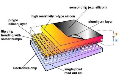 The Analog front end consists of a pre-amplifier followed by a window discriminator which has upper and lower threshold levels. The discriminator has four bits for threshold adjustment as well as polarity sensing. This allows the capture window to be precisely set. The rest of the digital electronics – multiplexers, shift registers, shutter and logic control – helps extract the data.