Design Tips To Hide Layer Lines In 3D Printed Parts

[Slant 3D] knows a lot about optimizing 3D prints so that they can be cranked out reliably with minimal need for post-processing, and in this short video he uses a cube as a simple example of how a few design changes can not only optimize for production, but can even hide layer lines pretty effectively.

Just to be perfectly clear, layer lines cannot be eliminated entirely without some kind of post-processing. But [Slant 3D]’s tips sure goes a long way toward making a part lose that obvious 3D-printed “look”. They also dovetail nicely with advice on how to optimize cranking out high numbers of parts in a print farm.

Adding texture to the outer layer is especially effective when combined with non-traditional part orientations.

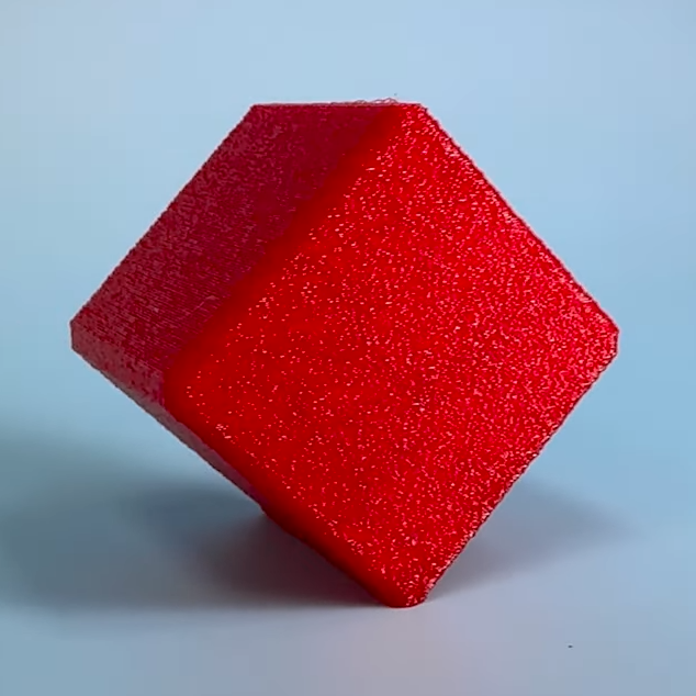
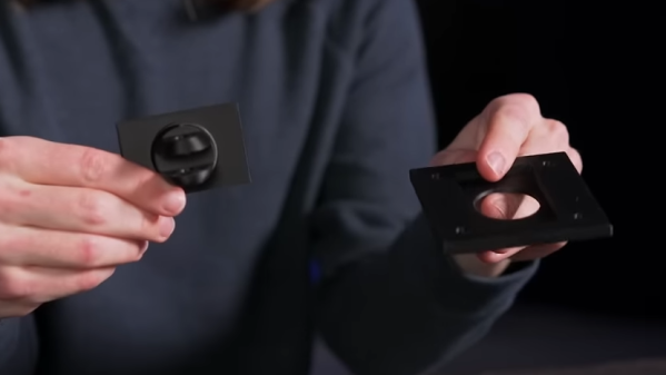
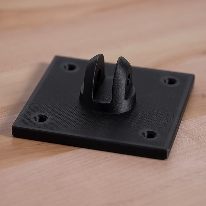
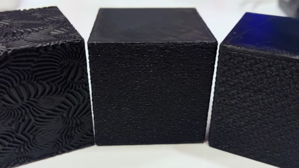
One simple way to avoid visible layer lines is to put some kind of texture onto the part. This can be modeled into the part’s surface, or the slicer software can be used to modify the exterior of the print to add a texture such as a geometric pattern or by applying a fuzzy skin modifier.

Printing a texture onto the exterior is great, but the outcome can be even further improved by also printing the object in a non-traditional orientation.

Using a cube as an example, printing the cube on a corner has the advantage of putting the layer lines in a different orientation as well as minimizing the contact area on the print bed. This applies the texture across more of the part, and looks less obviously 3D printed in the process. Minimizing bed adhesion also makes parts much easier to remove, which has obvious benefits for production. [Slant 3D] points out that performing these operations on a 3D-printed part is essentially free.

A few other optimizations for production involve rounding sharp corners to optimize tool travel paths, and putting a slight chamfer on the bottom of parts to avoid any elephant foot distortion (Elephant’s foot can be compensated for, but simply putting a slight chamfer on a part is a design change that helps avoid accounting for machine-to-machine variance.)

Even if one has no need to optimize for high production volume, the tips on hiding layer lines with design changes is great advice. Watch it all in action in the short video, embedded below.

Continue reading “Design Tips To Hide Layer Lines In 3D Printed Parts”

Lessons In Mass Production From An Atari Punk Console

Sometimes the most interesting part of a project isn’t the widget itself, but what it teaches you about the manufacturing process. The story of the manufacturing scale-up of this Atari Punk Console and the lessons learned along the way is a perfect example of this.

Now, don’t get us wrong — we love Atari Punk Consoles. Anything with a couple of 555s that bleeps and bloops is OK in our books. But as [Adam Gulyas] tells the tale, the point of this project was less about the circuit than about the process of making a small batch of something. The APC was low-hanging fruit in that regard, and after a quick round of breadboarding to decide on component values, it was off to production. [Adam] was shooting for 20 units, each in a nice enclosure and a classy package. PCB assemblies were ordered, as were off-the-shelf plastic enclosures, which ended up needing a lot of tweaking. [Adam] designed custom labels for the cases, itself a fraught job; glossy label stock and button bezels apparently don’t mix.

After slogging through the assembly process, boxing the units for shipping was the next job. [Adam] sourced jewelry boxes just a bit bigger than the finished APCs, and rather than settle for tissue paper or packing peanuts, designed an insert to hold the units snugly. That involved a lot of trial and error and a little bit of origami-fu, and the results are pretty nice. His cost per unit came out to just a hair over $20 Canadian, including the packaging, which is actually pretty remarkable for such a short production run.

[Adam] includes a list of improvements for larger-scale runs, including ordering assembled PCBs, outsourcing the printing processes, and getting custom boxes made so no insert is needed. Any way you cut it, this production run came out great and teaches us all some important lessons.

Lessons Learned: Plastic Injection Molding For Products

Injection molding is one of the technologies that makes the world go round. But what does it actually look like to go through the whole process to get a part made? [Achim Haug] wrote up a blog post that does a fantastic job of explaining what to expect when getting plastic enclosures injection molded in China.

These air quality monitors required a two-part enclosure.

Injection molding a part requires making a custom mold, which is then used by an injection molding machine in a shop to crank out parts. These are two separate jobs, but in China the typical business model is for a supplier to quote a price for both the mold as well as the part production. [Achim] describes not only what navigating that whole process was like, but also goes into detail on what important lessons were learned and shares important tips.

One of the biggest takeaways is to design the part with injection molding in mind right from the start. That means things like avoiding undercuts and changes in part thickness, as well as thinking about where the inevitable mold line will end up.

[Achim] found that hiring a been-there-done-that mold expert as a consultant to review things was a huge help, and well worth the money. As with any serious engineering undertaking, apparently small features or changes can have an outsized impact on costs, and an expert can recognize and navigate those.

In the end, [Achim] says that getting their air quality monitor enclosures injection molded was a great experience and they are very happy with the results, so long as one is willing to put the work in up front. Once the mold has been made, downstream changes can be very costly to make.

[Achim]’s beginning-to-end overview is bound to be useful to anyone looking to actually navigate the process, and we have a few other resources to point you to if you’re curious to learn more. There are basic design concerns to keep in mind when designing parts to make moving to injection molding easier. Some injection molding techniques have even proven useful for 3D printing, such as using crush ribs to accommodate inserted hardware like bearings. Finally, shadow lines can help give an enclosure a consistent look, while helping to conceal mold lines.

Splitting 3D Prints Into Parts Can Add Strength

One of the great things about 3D printers is their ability to make a single part all at once. Separating a part into multiple pieces is usually done to split up objects that are too big to fit on the 3D printer’s print bed. But [Peter] at Markforged (manufacturers of high-end 3D printers) has a video explaining another reason: multi-part prints can benefit from improved strength.

This part can be easily printed as a single piece, but it can be made nearly twice as strong when printed as two, and combined.

The idea is this: filament-based 3D printers generally create parts that are strongest along their X-Y axis (relative to their manufacture) and weakest in the Z direction. [Peter] proposes splitting a part into pieces with this in mind. Not because the part is inconveniently large or has tricky geometry, but so the individual pieces can be printed in orientations that provide the best mechanical strength.

This is demonstrated with the simple part shown here. The usual way to print this part would be flat on a print bed, but by splitting the parts into two and printing each in their optimal orientation, the combined part withstands nearly twice as much force before failing.

[Peter]’s examples use Markforged’s own filaments, but gives advice on more common polymers as well and the same principles apply. This idea is one worth keeping in mind the next time one is seeking to optimize strength. because of how simple it is.

We’ve seen a variety of methods to toughen up or ruggedize prints in the past, but they’re usually more complex (or at least messier.) Examples include embedding braided steel cable, embedding fiberglass mesh, applying electroplating to a printed structure, and plain old embedding some bolts and washers to buffer load-bearing areas.

Continue reading “Splitting 3D Prints Into Parts Can Add Strength”

Small synth held in two hands

3D Printed Synth Kit Shares Product Design Insights

We’ve always been delighted with the thoughtful and detailed write-ups that accompany each of [Tommy]’s synth products, and the background of his newest instrument, the Scout, is no exception. The Scout is specifically designed to be beginner-friendly, hackable, and uses 3D printed parts and components as much as possible. But there is much more to effectively using 3D printing as a production method than simply churning out parts. Everything needed to be carefully designed and tested, including the 3D printed battery holder, which we happen to think is a great idea.

3d printed battery holder, showing inserted spring contacts
3D printed battery holder, with spring contacts inserted by hand.

[Tommy] also spends some time explaining how he decided which features and design elements to include and which to leave out, contrasting the Scout with his POLY555 synth. Since the Scout is designed to be affordable and beginner-friendly, too many features can in fact be a drawback. Component costs go up, assembly becomes less straightforward, and more complex parts means additional failure points when 3D printing.

[Tommy] opted to keep the Scout tightly focused, but since it’s entirely open-sourced with a hackable design, adding features is made as easy as can be. [Tommy] designed the PCB in KiCad and used OpenSCAD for everything else. The Scout uses the ATmega328, and can be easily modified using the Arduino IDE.

STL files can be downloaded here and all source files are on the project’s GitHub repository, which also contains detailed assembly and modification guides. Watch it in action in the video, embedded below.

Continue reading “3D Printed Synth Kit Shares Product Design Insights”

To Lovers Of Small Boxes: A 3D Printable Design Just For You

Print them at 50% scale for a far cuter (and much less useful) result.

[Jacob Stanton]’s design for 3D-printable, stacking and locking boxes is a great example of design for manufacturability (DFM). MicroStacks show how part of good DFM is taking the manufacturing method’s strengths and weaknesses into account. [Jacob]’s boxes are created specifically with 3D printing in mind, which is great design whether somebody is making one, or dozens.

The boxes have sturdy parts that all print without any need for supports, fasteners, or post-processing. In addition, since no two 3D printers are quite alike and some print better than others, the parts are also designed to be quite forgiving of loose tolerances. Even on a printer that is less well-tuned than it could be, the design should still work. The boxes also have a nice stacking feature: a sturdy dovetail combined with a sliding tab means that once boxes are stacked, they’re not coming apart by accident unless something breaks in the process.

The boxes as designed are about big enough to store AA cells. Not the right size for you? One nice thing about a 3D-printable design that doesn’t need supports is that it’s trivial to uniformly scale the size of the models up or down to match one’s needs without introducing any print complications in the process. You can watch [Jacob] assemble and demonstrate his design in the video, embedded below.

Continue reading “To Lovers Of Small Boxes: A 3D Printable Design Just For You”

Peek Into This Synth’s Great Design (And Abandoned Features)

[Tommy]’s POLY555 is an analog, 20-note polyphonic synthesizer that makes heavy use of 3D printing and shows off some clever design. The POLY555, as well as [Tommy]’s earlier synth designs, are based around the 555 timer. But one 555 is one oscillator, which means only one note can be played at a time. To make the POLY555 polyphonic, [Tommy] took things to their logical extreme and simply added multiple 555s, expanding the capabilities while keeping the classic 555 synth heritage.

The real gem here is [Tommy]’s writeup. In it, he explains the various design choices and improvements that went into the POLY555, not just as an instrument, but as a kit intended to be produced and easy to assemble. Good DFM (Design For Manufacturability) takes time and effort, but pays off big time even for things made in relatively small quantities. Anything that reduces complexity, eliminates steps, or improves reliability is a change worth investigating.

For example, the volume wheel is not a thumbwheel pot. It is actually a 3D-printed piece attached to the same potentiometer that the 555s use for tuning; meaning one less part to keep track of in the bill of materials. It’s all a gold mine of tips for anyone looking at making more than just a handful of something, and a peek into the hard work that goes into designing something to be produced. [Tommy] even has a short section dedicated to abandoned or rejected ideas that didn’t make the cut, which is educational in itself. Want more? Good news! This isn’t the first time we’ve been delighted with [Tommy]’s prototyping and design discussions.

POLY555’s design files (OpenSCAD for enclosure and parts, and KiCad for schematic and PCB) as well as assembly guide are all available on GitHub, and STL files can be found on Thingiverse. [Tommy] sells partial and complete kits as well, so there’s something for everyone’s comfort level. Watch the POLY555 in action in the video, embedded below.

Continue reading “Peek Into This Synth’s Great Design (And Abandoned Features)”