Learn Flip Flops With Simulation

Digital design with combinatorial gates like AND, OR, and NOT gates is relatively straightforward. In particular, when you use these gates to form combinatorial logic, the outputs only depend on the inputs. The previous state of the outputs isn’t important in combinatorial logic. While this is simple, it also prevents you from building things like state machines, counters, and even CPUs.

Circuits that use their own outputs as inputs are known as sequential circuits. It is true that at the fundamental level, sequential circuits use conventional logic gates. However, you usually won’t deal with them as gates, but will deal with abstractions like latches, flip flops, and even higher level constructs. Learning about these higher level constructs will allow you to make more advanced digital designs that are robust. In fact, if you are using an FPGA, building blocks like flip flops are essential since a large portion of the chip will be made up of some kind of flip flop.

Continue reading “Learn Flip Flops With Simulation”

Need Timing Diagrams? Try Wavedrom

When working with anything digital, you’re going to end up reading or writing a timing diagram before long. For us, that’s meant keeping (text) notes, drawing something on a napkin, or using a tool like Inkscape. None of these are ideal.

An afternoon’s search for a better tool ended up with Wavedrom.

Just so you know where we’re coming from, here’s our list of desiderata for a timing diagram drawing solution:

  • Diagrams have a text-based representation, so their generation can be easily scripted and the results versioned and tracked throughout project development
  • Command-line rendering of images, because we like to automate everything
  • Looks good
  • Simple to use for common cases, but flexible enough to do some strange stuff when needed
  • Output modifiable when absolutely necessary: SVG would be nice

Basically, what we want is graphviz for timing diagrams.

Wavedrom nails four out of these five at the moment, and has promise to cover all of the bases. Give the online editor demo a try. We found it intuitive enough that we could make simple diagrams without even reading the fine manual. The tutorial has got you covered for more esoteric use cases.

foo

Clearly, some good thought has been put into the waveform description language, WaveJSON; it’s mostly readable and makes the essentials quick and easy. Because you can also enter straight SVG, it leaves the door open for full-fledged lunacy.

Wavedrom is written in JavaScript, and built for embedding in webpages; that’s the way they intend us to use it. On the other hand, if you want to run your own local version of the online editor, you can download it and install it locally if you’d like.

Our only quibble is that the standalone, command-line application wouldn’t generate images without the GUI on our Arch system. (Looks like there are some Google Chrome dependencies?) Otherwise, we think we’ve found our solution.

There are other applications out there. Drawtiming looks good, but we can’t quite get our head around the file format and the graphic output isn’t as flexible as we’d like: it only outputs GIF and we’re more into SVG because it can be edited easily after the fact.

There are font-based solutions that let you “type” the timing diagrams. We found Xwave and “Timing Diagram Font“. These work but aren’t particularly flexible; if you want something to happen at odd times, you’re out of luck. Plus, it just feels like a dirty hack, as if that were a bad thing.

Latex users can use tikz-timing, which makes sketching out your timing diagrams as much fun as laying out a very complex table in Latex (that is: not fun at all). On the other hand, it looks good, is ultimately flexible, outputs PDF, and would be scriptable if someone put the time in to write a nice frontend.

So for the next little while, we’re trying out Wavedrom.

What do you use for making timing diagrams?

Visualizing Digital Logic With EL Wire

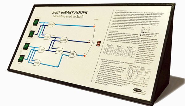
[Bob] and [Aubrey] run the System Source Computer Museum a little north of Baltimore, Maryland. For an exhibit, they thought a visual representation of digital logic and came up with a two-bit binary adder. Yes, it’s just a full adder and exactly what you would find somewhere in the second or third chapter of any digital logic textbook. The way they’re illustrating how a full adder works is the killer feature here: they’re using EL wire for all of the wires connecting the gates.

The full adder is implemented with an Arduino Mega, but the interface is the real show here. On the left side of the display there are four illuminated toggle switches that show virtual electrons flowing through EL wires, through gates and finally out to a seven-segment display. The EL wires are controlled with an EL Escudo Dos shield – a good thing, since there are a lot of lines between switches, gates, and outputs.

You can check out [Aubrey]’s demo video that also shows off how they built it below. If you’re around Baltimore, you can check out the display at the museum.

Continue reading “Visualizing Digital Logic With EL Wire”

Logic Simulator Atanua Goes Free, Possibly Open Source

The history of software is littered with developers that built a great product, gave people a reasonable option to license the software, and ended up making a pittance. There’s a reason you don’t see shareware these days – nobody pays. It looks like [Gates] had a point with his Open Letter to Hobbyists.

Such is the case with Atanua. [Jari] built a nice little graphical logic simulator that has tens of thousands of downloads, and is being used in dozens of universities. [Jari] has sold only about 60 licenses for Atanua, netting him only a few thousand Euro. You can’t develop software with a pittance, so now [Jari] is giving Atanua away. This neat little logic simulator has reached the end of its life, the license is free, and [Jari] is out of the business.

This isn’t an ideal situation, but [Jari] is strongly considering open-sourcing Atanua. The code is a little bit of a mess at the moment, and cleaning it up will require a bit of work. [Jari] is leaving the option to buy a license for Atanua open, and anyone who wants to see this bit of software open sourced could buy a license or hundred.

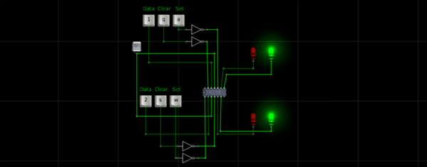
While this isn’t great news for [Jari], if you’re looking for a neat tool to learn digital logic, you now have a very nice free option. Atanua simulates individual logic gates, 74-series chips, and even an 8051 microcontroller in real-time (up to about 1 kHz), with enough buttons, LEDs, and displays to do some very cool stuff. It’s more than enough to learn digital logic on, and good enough for a test bed for some odd and bizarre projects you might have floating around your head.

Hackaday Links: January 12, 2014

hackaday-links-chain

[Kyle] teaches photography and after being dismayed at the shuttering of film and darkroom programs at schools the world over decided to create a resource for film photography. There’s a lot of cool stuff on here like mixing up a batch of Rodinal developer with Tylenol, lye, and sodium sulphite, and assessing flea market film cameras. There are more tutorials coming that will include setting up a dark room, developing prints, and playing around with large format cameras.

[hifatpeople] built a binary calculator out of LEGO® bricks or toys. It started off as a series of logic gates built out of LEGO® bricks or toys in the LEGO® Digital Designer. These logic gates were combined into half adders, the half adders combined into full adders, and the full adders combined into a huge plastic calculator. Unfortunately, buying the LEGO® bricks or toys necessary to turn this digital design into a physical model would cost about $1000 using the LEGO® Pick-A-Brick service. Does anyone have a ton of LEGO® Technic® bricks or toys sitting around? We’d love to see this built.

Think you need a PID controller and fancy electronics to do reflow soldering in a toaster oven? Not so, it seems. [Sivan] is just using a meter with a thermocouple, a kitchen timer, and a little bit of patience to reflow solder very easily.

The folks at DreamSourceLabs realized a lot of electronic test equipment – from oscilloscopes and logic analyzers to protocol and RF analyzers were all included a sampling circuit. They designed the DSLogic that puts a sampler and USB plug on one board, with a whole bunch of different tools connected to a pin header. It’s a pretty cool idea for a modular approach to test equipment.

Adafruit just released an iDevice game. It’s a resistor color code game and much more educational than Candy Crush. With a $0.99 coupon for the Adafruit store, it’s effectively free if you’re buying anything at Adafruit anytime soon. Check out the video and the awesome adorable component “muppets”.

MonoPong: A CMOS 1-D Pong

We’ve seen a few 1-D pong games recently, and they’ve all be controlled using microcontrollers. Inspired by some of these hacks, [mischka] built the monoPong using a handful of logic chips.

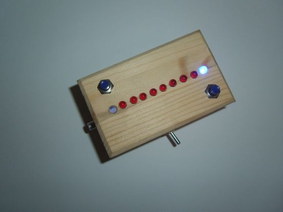
The monoPong has four major components. A 555 timer in astable mode provides a clock source which is fed into a 4510 decade counter, which connects to a 4028 BCD to decimal decoder to drive the LEDs. Finally, a 4011 NAND gate IC is used to deal with the button presses. Two of the NAND gates form a RS flip-flop, and the other two NAND each player’s button with the last LED on the player’s side of the strip. If the player hits the button when their LED is on, the RS flip-flop toggles and changes the decade counter from count up to count down mode. This makes the ball bounce back.

[mischka] finished the project off by putting it in a wooden box and drilling holes for the LEDs, buttons, and a power switch. The final product looks pretty good, and is a great example of how you can use a couple logic chips instead of a microcontroller.

After the break, watch a quick game of monoPong.

Continue reading “MonoPong: A CMOS 1-D Pong”

Bora Board Teaches Binary Hardware

If you’re just starting out in your quest to build really cool electronic devices, you’ll find a ton of options ready for the beginner. The Arduino makes toggling pins dead simple, and the Raspi brings the wonders of blinking a LED from the command line down from the gods and into the hands of the common man. These are all software platforms, though, and if you want to learn digital logic with hardware the best option is still a drawer full of 7400-series logic chips.

[Colin O’Flynn] hopes to change this with a beginners board for digital logic hardware design. It’s called the BORA, or Binary explORer boArd, and brings digital logic to a convenient package that is far less frustrating than a breadboard full of logic chips.

The BORA is based around a CPLD – a cousin of the FPGA-powered devices we see from time to time – that allows any student of digital logic to program the device and fill macrocells with NANDs, NORs, and ANDs.

The Xilinx device used in the BORA has about 1600 gates that can be programmed; more than enough to complete all the projects in the online lectures [Colin] has put together. You can check out the documentation for the BORA over on the official site, and the demo video after the break.

Continue reading “Bora Board Teaches Binary Hardware”