Home Made Diodes From Copper Oxide

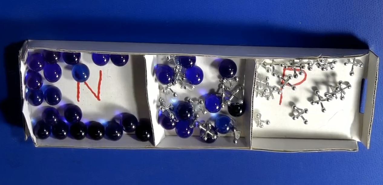
We’re all familiar with semiconductor devices, and we should remember the explanation from high-school physics classes that they contain junctions between two types of semiconductor material. “N” type which in the for-schoolchildren explanation has a surplus of electrons, and “P” type which has “Holes”, or a deficit of electrons.

Unless our careers have taken us deep into the science of the semiconductor industry though that’s probably as close as we’ve come to the semiconductors themselves. To us a diode or a transistor is a neatly packaged device with handy wires. We’ve never really seen what’s inside, let alone made any real semiconductor devices ourselves.

[Hales] though has other ideas. With the dream of creating a paintable semiconductor layer for ad-hoc creation of simple diodes, he’s been experimenting with oxidising copper to make a surface of cupric oxide onto which he can make a contact for a simple diode.

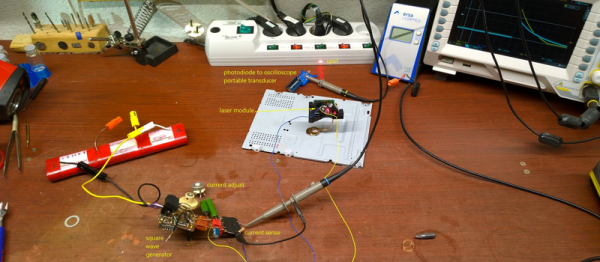
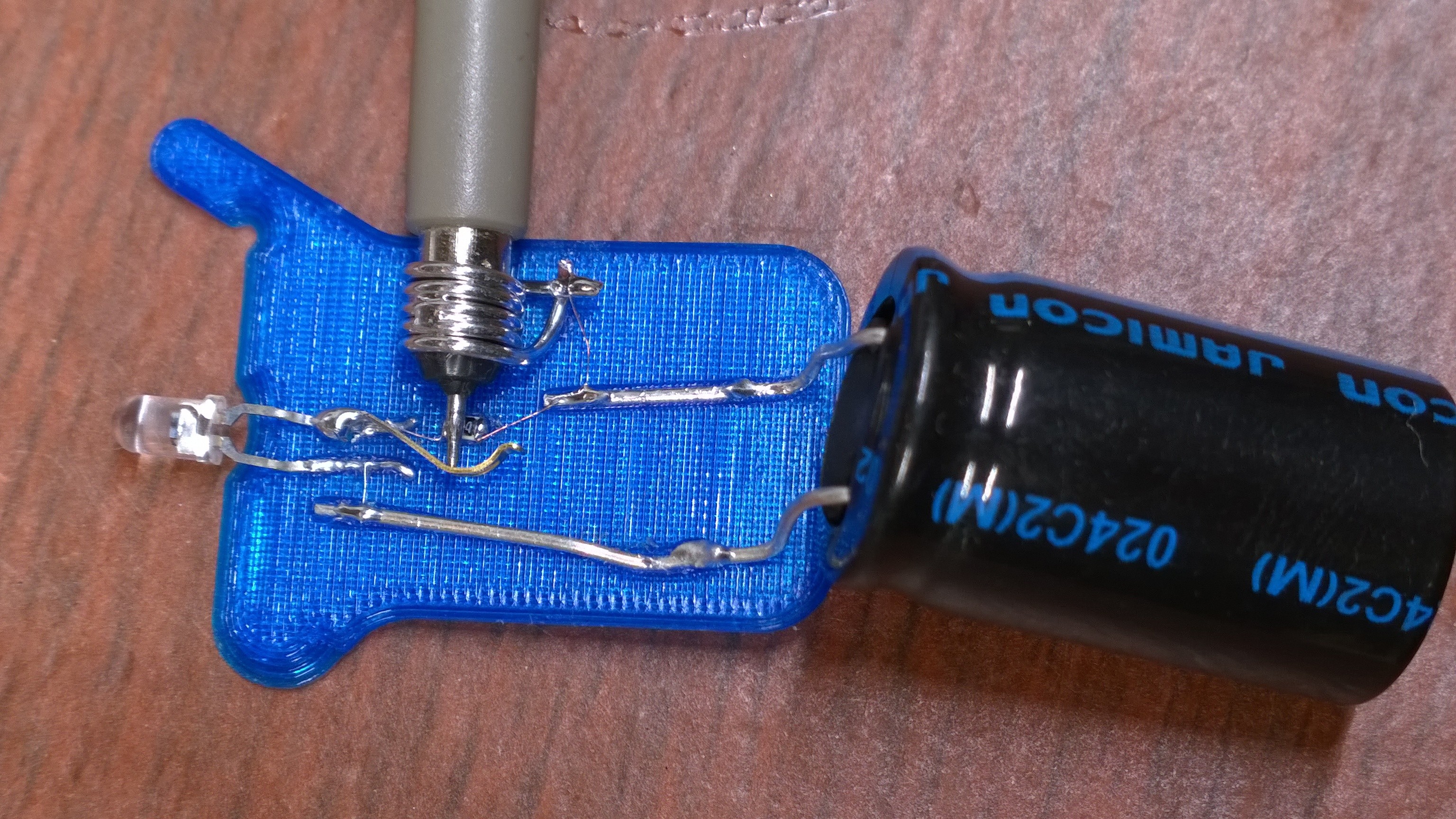
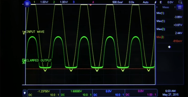
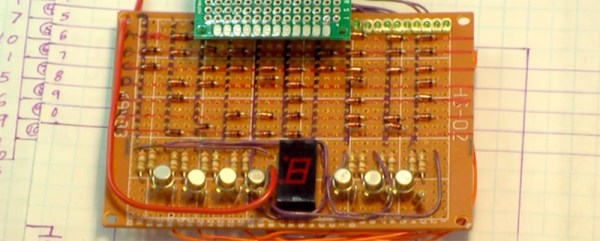
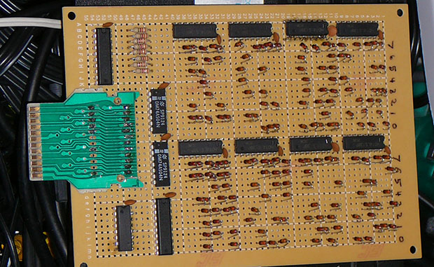
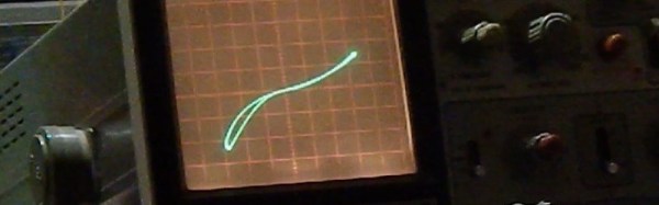
What makes his experiments particularly impressive though is not merely that he’s created a working diode, albeit one with a low reverse breakdown voltage. He’s done it not in a gleaming laboratory with a full stock of chemicals and equipment, but on his bench with a candle, and drops of water. He takes us through the whole process, with full details of his semiconductor manufacture as well as his diode test rig to trace the device’s I/V curve. Well worth a read, even if you never intend to make a diode yourself.

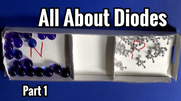
We’ve featured a cuprous oxide diode once before here at Hackaday, albeit a rather fancier device. If this article has piqued your interests about diodes, may we direct you to this informative video on the subject?

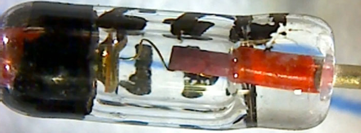
The diode looks black, leading me to believe it’s cupric oxide and not cuprous oxide. Feel free to argue that point in the comments anyway – Ed.

Sciencing DVD-RW Laser Diodes

If you’ve played around with laser diodes that you’ve scavenged from old equipment, you know that it can be a hit-or-miss proposition. (And if you haven’t, what are you waiting for?) Besides the real risk of killing the diode on extraction by either overheating it or zapping it with static electricity, there’s always the question of how much current to put into the thing.

[DeepSOIC] decided to answer the latter question — with science! — for a DVD-burner laser that he’s got. His apparatus is both low-tech and absolutely brilliant, and it looks like he’s getting good data. So let’s have a peek.

Laser Detector on 3D Printer Scrap

First up is the detector, which is nothing more than a photodiode, 100k ohm load resistor, and a big capacitor for a power supply. We’d use a coin-cell battery, but given how low the discharge currents are, the cap makes a great rechargeable alternative. The output of the photo diode goes straight into the scope probe.

He then points the photodiode at the laser spot (on a keyboard?) and pulses the laser by charging up a capacitor and discharging it through the laser and a resistor to limit total current. The instantaneous current through the laser diode is also measured on the scope. Plotting both the current drawn and the measured brightness from the photodiode gives him an L/I curve — “lumens” versus current.

laser_curve

Look on the curve for where it stops being a straight line, slightly before the wiggles set in. That’s about the maximum continuous operating current. It’s good practice to de-rate that to 90% just to be on the safe side. Here it looks like the maximum current is 280 mA, so you probably shouldn’t run above 250 mA for a long time. If the diode’s body gets hot, heatsink it.

If you want to know everything about lasers in general, and diode lasers in particular, you can’t beat Sam’s Laser FAQ. We love [DeepSOIC]’s testing rig, though, and would love to see the schematic of his test driver. We’ve used “Sam’s Laser Diode Test Supply 1” for years, and we love it, but a pulsed laser tester would be a cool addition to the lab.

What to do with your junk DVD-ROM laser? Use the other leftover parts to make a CNC engraver? But we don’t need to tell you what to do with lasers. Just don’t look into the beam with your remaining good eye!

Take The Long Road To A Precise Laser PCB Exposer

According to [diyouware], inside of every HD-DVD player is a gem of laser engineering with the designation of PHR-803T, and it’s just begging to be converted into a PCB exposer. Following along similar hacks which tore the laser diode out of Blu-ray players to expose PCBs, they wanted to use the whole PHR-803T unit without disassembling it, and to try to enable all of its unique features.

They envisioned something simple like a scanner for their machine. Just place the PCB on top of a glass sheet, close the lid, and click print. Unfortunately, moving the laser itself just caused too much vibration. So they switched to an inverted delta robot and named it TwinTeeth. In this design, the laser would stay still and the PCB would move.

What follows next is a seriously impressive journey in reverse engineering and design. The PHR-803T had no data sheet, but a ton of features. For example, it can autofocus, and has three different laser diodes. So many interesting problems were found and solved. For example, the halo from the laser caused the surrounding photoresist to cure. They solved it by adding a glass plate with a UV filtering film on it. Only the most focused point of the laser could punch through.

Another adventure was the autofocus. They wanted to autofocus on all four corners of the board. The PHR-803T was designed to read HD-DVDs so can focus a beam to far below 0.01 mm. They got autofocus working with the UV laser, but couldn’t use it on the PCB without curing the photoresist. So they put a piece of aluminum foil at a known level to start. Then they realized they could use the red or infrared diodes to focus instead. Now they can level the PCB in software, and focus the diode without curing the photoresist.

In the end they have an inverted-delta mini PCB factory. It can produce boards around the size of an Arduino shield with a resolution of 600 DPI. Their machine also has attachments for drilling and solder paste dispensing. Check out the video of it in action.
Continue reading “Take The Long Road To A Precise Laser PCB Exposer”

An Introduction To Zener Diodes

[Afroman] is back again with another great tutorial video on the basics of electronics. This time it’s zener diodes.

Page three or four of every ‘beginners guide to electronics’ covers a diode as, “a component that only allows current to flow in one direction.” This is true; a diode only allows current to flow in one direction. However, like any depth of knowledge, the dialectic of diodes quickly turns to a series of, ‘but..’ and ‘however…’ statements.

A zener diode is like a normal silicon diode, where a forward biased diode will pass current with a ~1 volt drop. When a zener diode is reversed biased, there’s a different voltage drop, annotated as Vz on the datasheet. When reversed biased, current cannot flow across the diode unless the voltage is above Vz. This is what makes zeners useful for a bunch of applications.

[Afroman] goes over a few of the most useful applications of zeners, including a diode clamping circuit. This circuit will clamp the voltage to a maximum of Vz, helpful when you’re feeding a signal into an analog input. This voltage clamping circuit can be used in some interesting applications. If you feed a sine wave or other signal though the circuit, you can clip the signal.

Zeners can also be used as a very crude, low current, low accuracy power supply. If you’re looking for a voltage regulator for a microcontroller that’s impossibly easy and you’re all out of 7805s, pick up a zener. It’s not the basis of a good power supply, but it does work.

Diode Steering And Counting With A 555

While you’re not likely to see this technique used very much today, there’s a lot you can do with a 555, some logic chips, and a handful of diodes. [Fran] is here with a great example of using these simple parts to build a circuit that counts to zero, using parts you can probably find under your workbench.

[Fran] was inspired to build this diode counter from one of [Dave]’s Mailbags and [Colin Mitchell]’s 555 circuit book. The 555 is the standard component found in every parts drawer, but since we have tiny microcontrollers that cost the same as a 555, we’re not seeing the artistry of a simple timer chip and a few logic chips much these days.

This circuit began with a 555 attached to a 4017B decade counter. Simply by tying a few LEDs to the output of the 4017, [Fran] made a bunch of LEDs light up in sequence. Cool, but nothing unexpected. The real trick uses a few diodes and six LEDs to build a scanner – a line of LEDs that will blink from left to right, then right to left. Impressive, and with a little more circuitry it’s a Larson Scanner, as seen in Battlestar Galactica and Knight Rider.

The real trick for this technique comes when [Fran] pulls out a piece of protoboard, several dozen diodes, and seven old transistors to have a seven-segment display count from zero to nine. The 4017 simply counts out on ten pins, and each of these pins is wired to a bunch of diodes for each segment in the display. Add in a few resistors and a transistor, and [Fran] replicated what’s inside a seven-segment driver with discrete parts.

If counting to zero isn’t enough proof that you can do a whole lot with some diodes and logic chips, how about programming an Atari 2600 with one?

Video below.

Continue reading “Diode Steering And Counting With A 555”

Homebrew Programming With Diodes

diode

Diode matrices were one of the first methods of implementing some sort of read only memory for the very first electronic computers, and even today they can be found buried deep in the IPs of ASICs and other devices that need some form of write-once memory. For the longest time, [Rick] has wanted to build a ROM out of a few hundred diodes, and he’s finally accomplished his goal. Even better, his diode matrix circuit is actually functional: it’s a 64-byte ROM for an Atari 2600 containing an extremely simple demo program.

[Rick] connected a ton of 1N60 diodes along a grid, corresponding to the data and address lines to the 2600’s CPU. At each intersection, the data lines were either unconnected, or tied together with a diode. Pulling an address line high or low ([Rick] hasn’t posted a schematic) pulls the data line to the same voltage if a diode is connected. Repeat this eight times for each byte, and you have possibly the most primitive form of read only memory.

As for the demo [Rick] coded up with diodes? It displays a rainbow of colors with a black rectangle that can be moved across the screen with the joystick. Video below.

Continue reading “Homebrew Programming With Diodes”

Video: The Lowly Diode — Umpteen Functions With Only Two Pins

The lowly diode, a device with only two leads, can nonetheless do many things. Diodes can detect, rectify, suppress, emit light, detect light, change capacitance, emit microwaves and more. This wide range of use means diodes are included in almost every design and it’s well worth learning more about the inner workings of all kinds of diodes.

My introduction to diodes started like many of my generation with a homemade crystal radio set. My first diode was a piece of pencil graphite in contact with an old fashion safety razor with the joint of the two dissimilar materials — graphite and steel — creating the diode. In this configuration the diode is said to be “detecting” which is the act of turning a weak radio signal into a weak audio signal. At least in my home town of Marion Indiana, one radio station was stronger than the other so that I didn’t have to listen to two stations at once.

Germanium Glass Diode
The venerable 1N34A Germanium Signal Diode.

I eventually learned about “real” diodes and the 1N34A Germanium diode was my “goto” diode into my teens. Nowadays looking into a modern version of the 1N34A you can still see the semblance of the old “cat’s whisker” by looking carefully into the diode.

A quick and somewhat inaccurate semblance of the way a diode works can be demonstrated with marbles and jacks representing negative electrons and positive “holes”. Holes are basically an atom missing an electron due to the combination of elements, a process known as doping. Join me after the break for the explanation.

Demonstrating a PN Junction with marbles and Jacks.

Continue reading “Video: The Lowly Diode — Umpteen Functions With Only Two Pins”