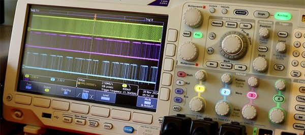
The Possibility Of Driving 16,000 RGB LEDs

Like just about everyone we know, [Luis] decided a gigantic RGB LED matrix would be a cool thing to build. Gigantic LED matrices are very hard to build, though: not only do you have to deal with large power requirements and the inevitable problems of overheating, you also need to drive a boat load of LEDs. This is not easy.

[Luis] found a solution to the problem of driving these LEDs with a new, fancy ARM Cortex M4 microcontroller. All Cortex M4 ARMs have DMA, making automatic memory transfers to peripherals and LED strips a breeze.

The microcontroler [Luis] is using only supports 1024 transfers per transfer set, equating to a maximum of 14 LEDs per transfer. This problem can be fixed by using the ping-pong mode in the DMA controller by switching between data structures for every DMA request. Basically, he’s extending the number of LEDs is just switching between two regions of memory and setting up the DMA transfer.

The result is much better than [Luis]’ original circuit that was just a bunch of SPI lines. It also looks really good, judging by the video below. It’s not quite a gigantic LED matrix yet, but if you want to see what that would look like, check out the huge 6 by 4 foot matrix hanging in the Hackaday overlord office.

Continue reading “The Possibility Of Driving 16,000 RGB LEDs”

12 Mbps Communication Between A PC And MCU

The world of hobby electronics have only started putting USB in projects for the last few years, and right now, pushing 1.5 Mbps down a USB port is good enough for most cases. This isn’t true for all cases; that’s a terrible data rate, really, and to get the most out of a USB connection, you can at least move up to USB Full Speed and 12 Mbps.

[Linas] is using the STM32F4 microcontroller for this example, an extremely large and very capable chip. [Linas] is using FTDI’s FT2232D USB UART to send data from an SPI port over USB. This chip does support 12 Mbps, but only after a few additions; an external EEPROM must be connected to the FTDI chip to provide a USB 2.0 device descriptor, otherwise the connection between the microcontroller and a computer is limited to 1.5 Mbps. Even using the USB on the STM32 would be a bottleneck in this case; [Linas] is moving data out of the processor using only the DMA controller – using the USB on the STM32 would eat up processor cycles in the microcontroller.

Thanks to the DMA controller inside the STM32, the microcontroller is capable of sending and receiving data through SPI at the same time. The STM32 is capable of reading and writing to the Tx and Rx buffer at the same time, but the computer is only capable of half-duplex operation – it can only read or write at any one time. [Linas] is setting up the DMA controller on the STM32 as a circular mode, putting everything in the buffer into the FTDI chip, and reading everything sent from the computer back into the STM32’s memory. After counting off the correct number of packets. the controller resets everything, moves the circular buffer back to the beginning, and starts the whole process over again.

The circuit was prototyped with an STM Discovery board. With Labview, [Linas] can see the bits coming out of the microcontroller, and send some bits back to the micro over USB. [Linas] has an extraordinarily detailed video tutorial on this project. You can check that out below.

Continue reading “12 Mbps Communication Between A PC And MCU”