A raspberry pi-based digital readout above an old lathe

Roll Your Own DRO With An Added Twist

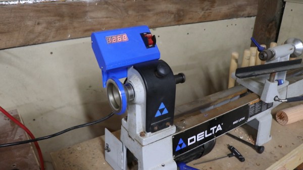
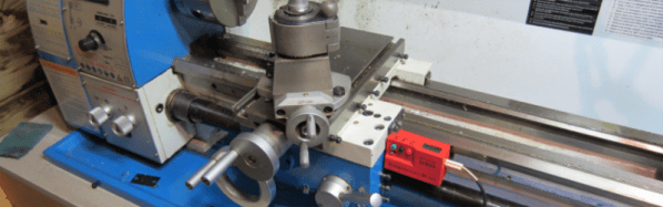
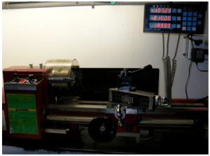
When using a manual machine tool such as a lathe or milling machine, there can be a lot of pressure to read the position and feed the axes at the correct rate. That’s why modern machines typically have some form of digital read-out (DRO). [Stefano Bertelli] has created a simple Raspberry Pi based DRO with an additional twist, that of a linked motor drive output.

A view of the custom RS485 interfaced DRO readout and motor controller
Realtime encoder position reading and motor control are best done with a dedicated microcontroller, ideally with a proper RTOS.

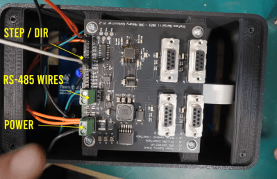
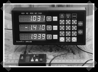
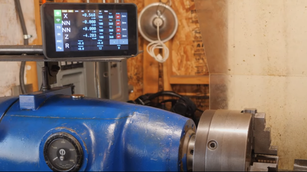
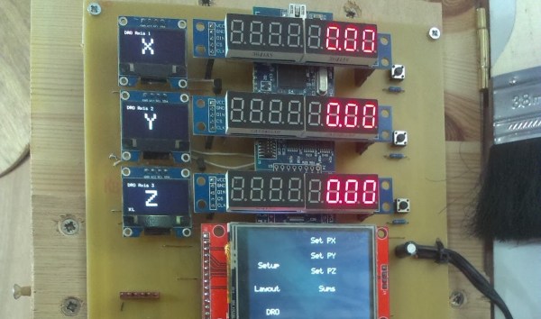
The axes that need to be monitored should be mechanically attached to a position sensor like a linear encoder or a rotary type. Using a linear sensor with a linear axis instead of a rotary encoder on the downstream dial is better. For the readout unit, [Stefano] used a WaveShare 7-inch touchscreen module with a Raspberry Pi 3 for the UI of the readout unit. The Pi has a custom-designed HAT, that performs power conditioning and provides a robust RS485 interface. Connected via that RS485 link is another custom PCB based on an STM32F411 with a few supporting power supplies and interfacing components. The job of this board is to interface to the position encoders, reading positioning pulses using interrupts. There is an additional stepper motor drive courtesy of a ULN2003 Darlington driver to allow the control of a single motorised axis. An additional motor driver module is required, which should be no surprise since driving a milling machine axis will require a fairly beefy motor. This GitHub repo contains the FreeRTOS-based firmware for this board. This motor drive has the ability to be connected to a measuring axis in a programmable way, enabling one axis to be adjusted to follow or jump in controlled steps with another. This feature can significantly simplify certain types of machining operations, as [Stefano] elaborates in the video.

Lastly, the Raspberry Pi runs a simple Python application with Kivy for the GUI. As [Stefano] explains in the video below, this makes debugging and modification quite simple.

Adding DROs to an older machine is an obvious but valuable hack. Here’s another way to do it. If that’s too much work, then you could just hack a digital readout calliper in there.

Continue reading “Roll Your Own DRO With An Added Twist”

Adding A Digital Readout To A Wood Lathe

The benefit of living in the modern era is that there are plenty of affordable machine tools on the market for the budding maker. However, to meet lower price points, products often forgo some of the nice-to-have features that make working easier. Of course, if you’ve got the skills to do it yourself, this needn’t be a problem, as [Zach] demonstrates.

[Zach] enjoyed using his wood lathe, but it didn’t come with a digital readout. Thankfully, retrofitting one was an easy, straightforward project. After a little research, a Hall effect sensor was chosen to detect the rotational speed of the lathe. The spindle was thus fitted with several magnets to trigger the sensor, allowing for higher resolution than just using a single device. An Arduino Nano was then used to monitor the output of the Hall effect sensor, displaying the rotational speed on a set of 7-segment displays. The project was then given its own custom PCB, and a nice 3D printed enclosure to fit it to the body of the lathe.

It’s a project that shows how easy it is to add functionality to basic machine tools using maker components. It also serves to demonstrate the value in giving a project a proper enclosure, to enable it to survive in a workshop environment. We’ve seen other hacky DRO mods before, too. Video after the break.

Continue reading “Adding A Digital Readout To A Wood Lathe”

Hackaday Prize Entry: Mini DRO For A Lathe

A manual lathe has dial wheels to control the feed of the main carriage and the cross slide to help take cuts on the workpiece. These feed wheels always have some backlash and require frequent resetting of the “zero”. The usual process would be to take measurements on the workpiece with either a vernier caliper or a micrometer at intervals which requires stopping the machine, adding up to increased machine time. The addition of a digital readout not only simplifies the process, but also reduces machining time substantially. Since the DRO magnetic strips are directly attached to the cross slide, the effects of backlash are mitigated.

[Igor] has just such a manual lathe and built his own mini DRO unit from scratch a couple of years back. Most DRO’s have encoder strips and sensors attached to the cross slide with a larger display unit attached separately on a stalk, with wires running between the two. [Igor] kept things simple by building a unit that fit within the space constraints he had. His unit consists of just two sensor modules – each attached directly to the slide. The main unit houses a linear hall sensor, electronics, buttons, a small LCD and batteries. The second axis unit houses just the sensor with a cable connecting it to the main unit for data and power. At the heart of the system is a pair of NSE-5310 linear hall sensor encoder chips. These work in conjunction with multipole magnetic strips. The encoder provides a 12-bit output, and the magnetic strips have poles spaced 2 mm apart. This translates to a theoretical resolution of almost 0.5 microns, but of course, the machine mechanics limit the actual results. The encoder chips talk to an ATtiny2313 over the I2C bus. Three buttons and the power supply round-up the hardware. To run it off a single 1.5 V rechargeable battery, [Igor] used a boost converter to get 3.3 V. The 5 V needed for the LCD is obtained by a voltage doubler connected to a PWM output from the microcontroller and regulated by a Zener diode. The second sensor unit connects via a TRRS 3.5 mm socket.

He added a Bluetooth module as an after thought, but ran out of GPIO pins as well as program space and had to get creative to make it work. The plan was to transmit the data to an Android tablet which would work as a large, remote, wireless display. He never did use that feature though, being satisfied with the small LCD display. There’s several things that went wrong in the build, and if he were to replicate the project again, several changes and improvements would help. So if anyone plans on doing something similar, do check up [Igor]’s project logs first.

Making An Inexpensive DRO

[Andrew] wanted a digital readout (DRO) for his mini lathe and mini mill, but found that buying even one DRO cost as much as either of his machines. The solution? You guessed it, he built his own for cheap, using inexpensive digital calipers purchased off eBay.

The DRO he created features a touch screen with a menu system running on an LPCXpresso, while smaller OLED screens serve as labels for the 7-segment displays to the right. The DRO switches back and forth between the lathe and mill, and while the software isn’t done, [Andrew] hopes to be able to transfer measurements from one machine to the other.

In a very sweet touch, [Andrew] hacked cheap digital calipers to provide measurements for each axis, where they provide a resolution of 0.01mm. There are six daughter boards, one for each caliper, and each has a PIC that converts from serial to I2C, freeing the main firmware from dealing with six separate data streams.

The DRO doesn’t have a case, [Andrew] has it positioned out of chip-range from either machine.

A previous DRO we featured in 2012 used an Android tablet as its display.

Super Cheap Super Simple DRO

If you have an old manual lathe, mill, or even a drill press, a digital readout (DRO) is a very handy tool to have. A DRO gives you a readout of how far you’ve cut, milled, or drilled into a piece of work without having to stoop to caveman levels and look down at a dial. Here’s a stupidly cheap DRO for all your machine tools. It should only cost five bucks or so, and if you need it, you already have the tools to manufacture it.

This build is inspired by an earlier build using the same single component – a digital tread depth gauge. This digital tread depth gauge is commonly found in countries that don’t use the US penny as currency to measure the depth of tread on a tire. The throw isn’t that large – only about 27mm – but with a few modifications it can fit on any machine tool.

The modifications include a small bit of metal glued to the back and four tiny neodymium magnets.  For the ‘tool head’ of this DRO, only a tiny plastic collar and another deo magnet are needed.

This digital tire depth gauge looks like – and probably is – the same mechanism found in those super cheap calipers from the far east. In theory, it should be possible to extend this modification to those digital calipers, making for a simple DRO with a much larger throw.

Thanks [Ben] for sending this one in.

DIY Lathe DRO

Digital Caliper Sacrificed For DRO Project

In general, machining metal on a lathe or mill takes skill and patience as the accuracy of the cuts are important. To make those accurate cuts, it is important to know where the tool is located and how far it moves. For manual machines, the most basic method of determining position is by using graduated dials mounted on the hand cranks. Although these graduated dials can certainly be accurate, they may be difficult to see and they also require the operator to do math in their head on the fly with every full revolution of the dial. Another option would be a digital read out (DRO) which has an encoder mounted to the moving axes of the machine. This setup displays the exact position of the tool on an easy to read numeric display.

Professional DRO kits for mills and lathes can cost between a few hundred dollars to several thousand dollars.  [Robert] has a lathe, wanted a DRO but didn’t want to shell out serious cash to get it. He built his own for super cheap in an extremely resourceful way…. using a Harbor Freight Digital Caliper. A housing was first fabricated so that the added equipment would not hinder the axis travel of the lathe. The caliper was then cut to length, installed in the housing and the entire assembly was then mounted to the lathe.

DIY Lathe DRO
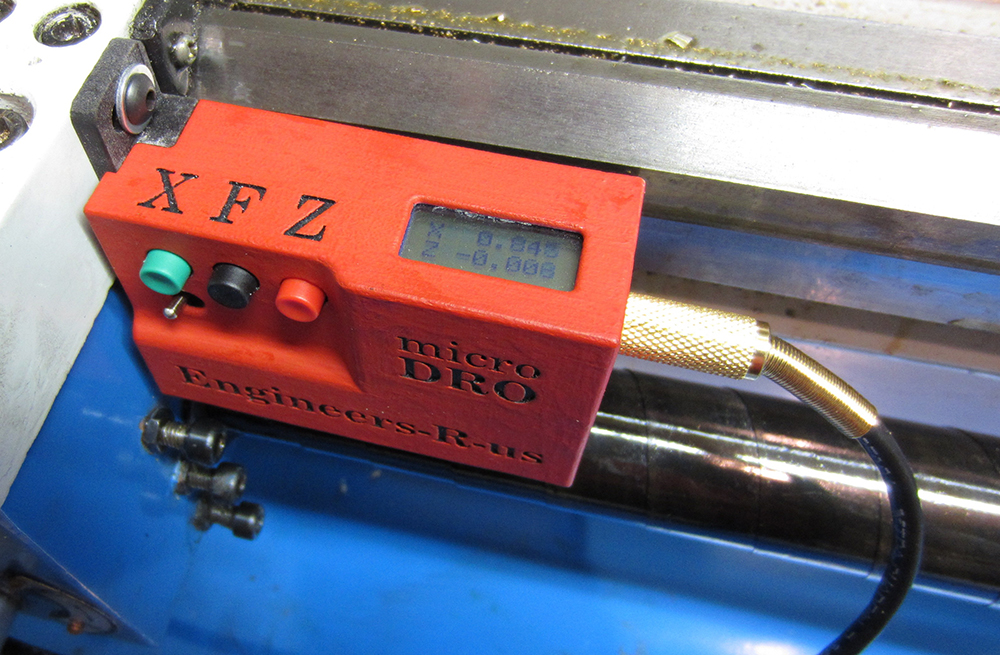
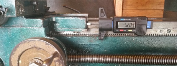
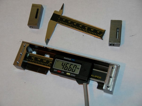
It is totally reasonable to use the stock caliper display to read the positional information, however, even these cheap digital calipers have connections for the encoder output data, which can easily be read by a microcontroller. That means it is super simple to hook these low-cost digital calipers up to a display remotely located in a more convenient position.


Digital Caliper Modding


This particular hack is actually used in a kit design, but it’s still pretty sweet. This is a digital read out unit that’s a kit sold by shumatech. I’ve even mentioned it in passing before. The design takes in the pulses from inexpensive chinese made digital scales/calipers, and allows one stop calibration and ouput of three axis’s of measurement. Using the interface and a usb enabled pic, and you could make your own usb digital calipers… (Hmm, I might have to make some.)