The sound produced by any given electric guitar is shaped not just by the instrument itself but by the amplifiers chosen to make that sound audible. Plenty of musicians swear by the warm sound of amplifiers with vacuum tube circuits, but they do have some limitations. [Collin] wanted to build a reactive load for using tube amps without generating a huge quantity of sound, and it resulted in an interesting project that also taught him a lot about inductors.
The reactive load is essentially a dummy load for the amplifier that replaces a speaker with something that won’t produce sound. Passive loads typically use resistor banks but since this one is active, it needs a very large inductor to handle the amount of current being produced by the amplifier. [Colin] has also built a headphone output into this load which allows it to output a much smaller quantity of sound to a headset while retaining the sound and feel of the amplifier tubes, and it additionally includes a widely-used tone control circuit as well.
There’s a lot going on in the design of the circuitry for this amplifier load, including a lot of research into low-frequency inductors that can handle a significant amount of current. [Collin] eventually ended up winding his own, but the path he took to it was long and winding. There’s a lot of other circuit theory discussed as well especially with regards to the Baxandall EQ that he built into it as well. And, if you’d like to learn more about tube amplifiers in general, take a look at this piece which notes one of the best stereo amps ever produced.
The epicenter of the Chinese electronics scene drew a lot of attention this week as a 70-story skyscraper started wobbling in exactly the way skyscrapers shouldn’t. The 1,000-ft (305-m) SEG Plaza tower in Shenzhen began its unexpected movements on Tuesday morning, causing a bit of a panic as people ran for their lives. With no earthquakes or severe weather events in the area, there’s no clear cause for the shaking, which was clearly visible from the outside of the building in some of the videos shot by brave souls on the sidewalks below. The preliminary investigation declared the building safe and blamed the shaking on a combination of wind, vibration from a subway line under the building, and a rapid change in outside temperature, all of which we’d suspect would have occurred at some point in the 21-year history of the building. Others are speculating that a Kármán vortex Street, an aerodynamic phenomenon that has been known to catastrophically impact structures before, could be to blame; this seems a bit more likely to us. Regardless, since the first ten floors of SEG Plaza are home to one of the larger electronics markets in Shenzhen, we hope this is resolved quickly and that all our friends there remain safe.
In other architectural news, perched atop Building 54 at the Massachusetts Institute of Technology campus in Cambridge for the last 55 years has been a large, fiberglass geodesic sphere, known simply as The Radome. It’s visible from all over campus, and beyond; we used to work in Kendall Square, and the golf-ball-like structure was an important landmark for navigating the complex streets of Cambridge. The Radome was originally used for experiments with weather radar, but fell out of use as the technology it helped invent moved on. That led to plans to remove the iconic structure, which consequently kicked off a “Save the Radome” campaign. The effort is being led by the students and faculty members of the MIT Radio Society, who have put the radome to good use over the years — it currently houses an amateur radio repeater, and the Radio Society uses the dish within it to conduct Earth-Moon-Earth (EME) microwave communications experiments. The students are serious — they applied for and received a $1.6-million grant from Amateur Radio Digital Communications (ARDC) to finance their efforts. The funds will be used to renovate the deteriorating structure.
Well, this looks like fun: Python on a graphing calculator. Texas Instruments has announced that their TI-84 Plus CE Python graphing calculator uses a modified version of CircuitPython. They’ve included seven modules, mostly related to math and time, but also a suite of TI-specific modules that interact with the calculator hardware. The Python version of the calculator doesn’t seem to be for sale in the US yet, although the UK site does have a few “where to buy” entries listed. It’ll be interesting to see the hacks that come from this when these are readily available.
Did you know that PCBWay, the prolific producer of cheap PCBs, also offers 3D-printing services too? We admit that we did not know that, and were therefore doubly surprised to learn that they also offer SLA resin printing. But what’s really surprising is the quality of their clear resin prints, at least the ones shown on this Twitter thread. As one commenter noted, these look more like machined acrylic than resin prints. Digging deeper into PCBWay’s offerings, which not only includes all kinds of 3D printing but CNC machining, sheet metal fabrication, and even injection molding services, it’s becoming harder and harder to justify keeping those capabilities in-house, even for the home gamer. Although with what we’ve learned about supply chain fragility over the last year, we don’t want to give up the ability to make parts locally just yet.
And finally, how well-calibrated are your fingers? If they’re just right, perhaps you can put them to use for quick and dirty RF power measurements. And this is really quick and really dirty, as well as potentially really painful. It comes by way of amateur radio operator VK3YE, who simply uses a resistive dummy load connected to a transmitter and his fingers to monitor the heat generated while keying up the radio. He times how long it takes to not be able to tolerate the pain anymore, plots that against the power used, and comes up with a rough calibration curve that lets him measure the output of an unknown signal. It’s brilliantly janky, but given some of the burns we’ve suffered accidentally while pursuing this hobby, we’d just as soon find another way to measure RF power.
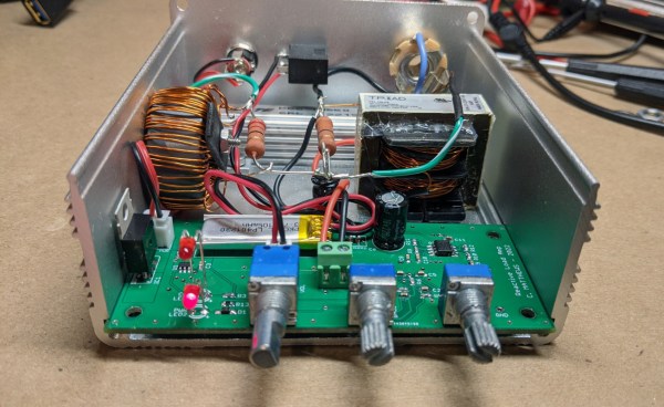
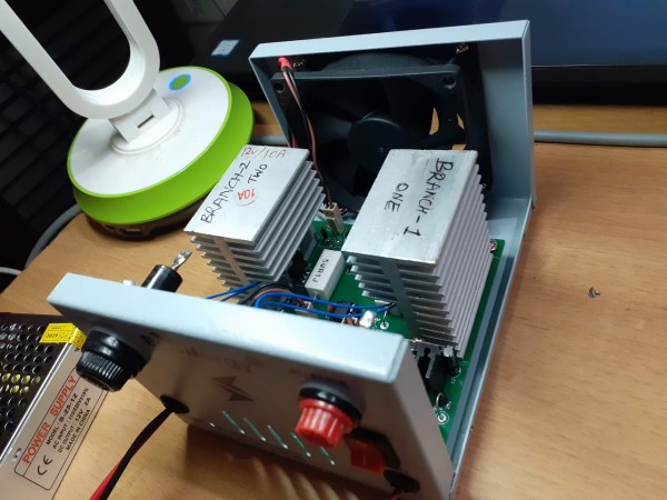
While it might seem counterintuitive on the surface, there are a number of cases where dumping a large amount of energy into a resistor simply to turn it into heat is necessary to the operation of a circuit. Most of these cases involve testing electronic equipment such as power supplies or radio transmitters and while a simple resistor bank can be used in some situations, this active dummy load is comprised of different internals has some extra features to boot.
The load bank built by [Debraj] is actually an electronic load, which opens it up for a wider set of use cases than a simple passive dummy load like a resistor bank. It’s specifically designed for DC and also includes voltage measurement, current control, and temperature measurement and speed control of the fans on the heat sinks. It also includes a Bluetooth module that allows it to communicate to a computer using python via a custom protocol and GUI.
While this one does use a case and some other parts from another product and was specifically built to use them, the PCB schematics and code are all available to build your own or expand on this design. It’s intended for DC applications, but there are other dummy loads available for things such radio antenna design, and it turns out that you can learn a lot from them too.
In the last installment of “The $50 Ham” I built a common tool used by amateur radio operators who are doing any kind of tuning or testing of transmitters: a dummy load. That build resulted in “L’il Dummy”, a small dummy load intended for testing typical VHF-UHF handy talkie (HT) transceivers, screwing directly into the antenna jack on the radio.
As mentioned in the comments by some readers, L’il Dummy has little real utility. There’s actually not much call for a dummy load that screws right into an HT, and it was pointed out that a proper dummy load is commercially available on the cheap. I think the latter observation is missing the point of homebrewing specifically and the Hackaday ethos in general, but I will concede the former point. That’s why at the same time I was building L’il Dummy, I was building the bigger, somewhat more capable version described here: Big Dummy.
This is an exciting day for me — we finally get to build some ham radio gear! To me, building gear is the big attraction of amateur radio as a hobby. Sure, it’s cool to buy a radio, even a cheap one, and be able to hit a repeater that you think is unreachable. Or on the other end of the money spectrum, using a Yaesu or Kenwood HF rig with a linear amp and big beam antenna to work someone in Antartica must be pretty cool, too. But neither of those feats require much in the way of electronics knowledge or skill, and at the end of the day, that’s why I got into amateur radio in the first place — to learn more about electronics.
To get my homebrewer’s feet wet, I chose perhaps the simplest of ham radio projects: dummy loads. Every ham eventually needs a dummy load, which is basically a circuit that looks like an antenna to a transmitter but dissipates the energy as heat instead of radiating it an appreciable distance. They allow operators to test gear and make adjustments while staying legal on emission. Al Williams covered the basics of dummy loads a few years back in case you need a little more background.
We’ll be building two dummy loads: a lower-power one specifically for my handy talkies (HTs) will be the subject of this article, while a bigger, oil-filled “cantenna” load for use with higher power transmitters will follow. Neither of my designs is original, of course; borrowing circuits from other hams is expected, after all. But I did put my own twist on each, and you should do the same thing. These builds are covered in depth on my Hackaday.io page, but join me below for the gist on a good one: the L’il Dummy.
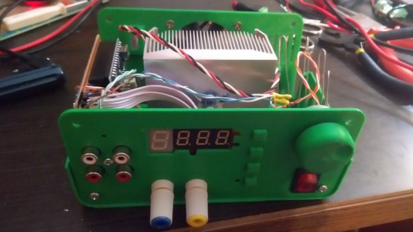
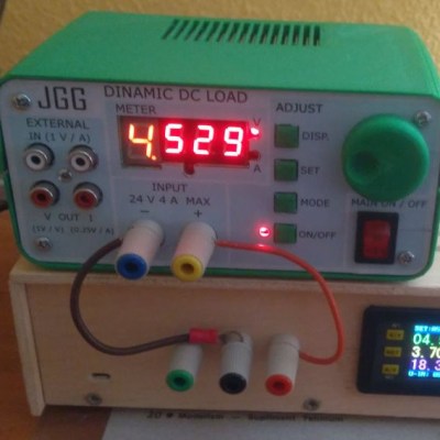
Sometimes it’s necessary to make do with whatever parts one has on hand, but the results of squashing a square peg into a round hole are not always as elegant as [Juan Gg]’s programmable DC load with rotary encoder. [Juan] took a design for a programmable DC load and made it his own in quite a few different ways, including a slick 3D-printed enclosure and color faceplate.
The first thing to catch one’s eye might be that leftmost seven-segment digit. There is a simple reason it doesn’t match its neighbors: [Juan] had to use what he had available, and that meant a mismatched digit. Fortunately, 3D printing one’s own enclosure meant it could be gracefully worked into the design, instead of getting a Dremel or utility knife involved. The next is a bit less obvious: the display lacked a decimal point in the second digit position, so an LED tucked in underneath does the job. Finally, the knob on the right could reasonably be thought to be a rotary encoder, but it’s actually connected to a small DC motor. By biasing the motor with a small DC voltage applied to one lead and reading the resulting voltage from the other, the knob’s speed and direction can be detected, doing a serviceable job as rotary encoder substitute.
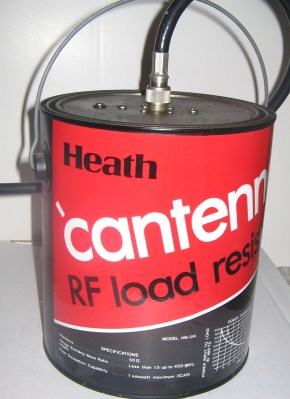
If you work on RF circuits–even if you aren’t a ham radio operator–you ought to have a dummy load. A dummy load is a non-radiative “antenna” with known impedance that you can use to test your RF circuit without radiating. For radio work, you usually just need a 50-ohm resistor that is non-inductive (at least at the frequencies you are interested in) and that can dissipate the amount of power you’ll expect it to handle (at least for a short time). [VO1PWF] wanted a dummy load and built his own. The Cantenna (not the Pringle’s kind; see right) was a famous dummy load design when Heathkit was in business. It was a single carbon rod immersed in a paint can full transformer oil (which we now know was full of dangerous PCBs; and we don’t mean printed circuit boards). [VO1PWF’s] design is a little more practical, using some resistors in parallel (20 1K resistors), a plastic pipe housing, and mineral oil to keep it all cool.
The reason for the parallel resistors is to maximize the power handling capability. The resistors are 3W units, so the dummy load–in theory–can handle 60 watts. Often, high power resistors are wire wound and thus have a good bit of parasitic inductance that makes the dummy load reactive (not a good thing since that makes the load impedance vary by frequency). They do make non-inductive wire wound resistors, but these aren’t truly non-inductive. The wire winds in two different directions, so the inductance tends to cancel out. We wouldn’t trust them to be a pure resistance in a high-power dummy load design.


 The first thing to catch one’s eye might be that leftmost seven-segment digit. There is a simple reason it doesn’t match its neighbors: [Juan] had to use what he had available, and that meant a mismatched digit. Fortunately, 3D printing one’s own enclosure meant it could be gracefully worked into the design, instead of getting a Dremel or utility knife involved. The next is a bit less obvious: the display lacked a decimal point in the second digit position, so an LED tucked in underneath does the job. Finally, the knob on the right could reasonably be thought to be a rotary encoder, but it’s actually connected to a small DC motor. By biasing the motor with a small DC voltage applied to one lead and reading the resulting voltage from the other, the knob’s speed and direction can be detected, doing a serviceable job as rotary encoder substitute.
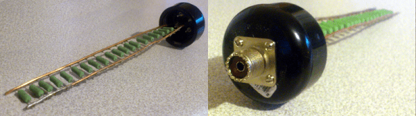
 The Cantenna (not the Pringle’s kind; see right) was a famous dummy load design when Heathkit was in business. It was a single carbon rod immersed in a paint can full transformer oil (which we now know was full of


