A view of the inside of a car, with drivers wheel on the left and control panel in the middle, with red LED light displayed in the floor area under the drivers wheel and passenger side.

Bass Reactive LEDs For Your Car

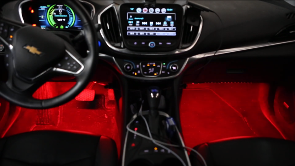
[Stephen Carey] wanted to spruce up his car with sound reactive LEDs but couldn’t quite find the right project online. Instead, he wound up assembling a custom bass reactive LED display using an ESP32.

A schematic of the Bass LED reactive circuit, with an ESP32 on a breadboard connected to a KY-040 encoder module, a GY-MAX4466 microphone module and LED strips below.

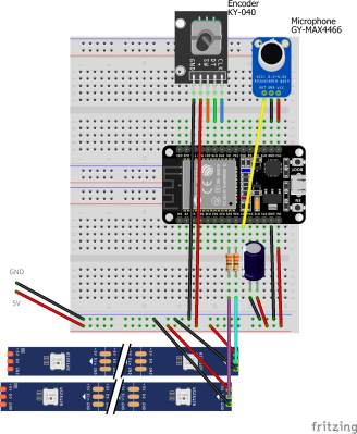
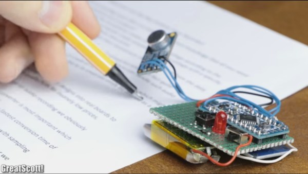
The entirety of the build is minimal, consisting of a GY-MAX4466 electret microphone module, a KY-040 encoder for some user control and an ESP32 attached to a Neopixel strip. The only additional electronic parts are some passive resistors to limit current on the data lines and a capacitor for power line noise suppression. [Stephen] uses various enclosures from Thingiverse for the microphone, rotary encoder and ESP32 box to make sure all the modules are protected and accessible.

The magic, of course, is in the software, with the CircuitPythyon ulab library used to do the heavy lifting of creating the spectrogram and frequency filtering. [Stephen] has made the code is available on GitHub for those wanting to take a closer look.

It wasn’t very long ago that sound reactive LEDs used to be a heavy lift, requiring optimized FFT libraries or specialized components to do the spectrogram. With faster and cheaper microcontroller boards, we’re seeing many great projects, like the sensory bridge or Raspberry Pi driven LED spectrogram, that can now take spectrograms and Fourier transform calculations as basic infrastructure to build on top of them. We’re happy to see [Stephen] leverage the ESP32’s speed and various circuit Python libraries to create a very cool LED car hack.

Video after the break!

Continue reading “Bass Reactive LEDs For Your Car”

James West Began 40 Years At Bell Labs With World-Changing Microphone Tech

I’d be surprised if you weren’t sitting within fifty feet of one of James Edward Maceo West’s most well-known inventions — the electret microphone. Although MEMS microphones have seen a dramatic rise as smartphone technology progresses, electret microphones still sit atop the throne of low-cost and high-performance when it comes to capturing audio. What’s surprising about this world-changing invention is that the collaboration with co-inventor Gerhard Sessler began while James West was still at university, with the final version of the electret springing to life at Bell Labs just four years after his graduation.

A Hacker’s Upbringing

James’ approach to learning sounds very familiar: “If I had a screwdriver and a pair of pliers, anything that could be opened was in danger. I had this need to know what was inside.” He mentions a compulsive need to understand how things work, and an inability to move on until he has unlocked that knowledge. Born in 1931, an early brush with mains voltage started him on his journey.

Continue reading “James West Began 40 Years At Bell Labs With World-Changing Microphone Tech”

Building A Top-Notch Electret Microphone

Electret microphones are capable of high-quality output, and are prized for their smooth frequency response. However, unlike other types, they can’t simply be plugged directly into a mixing desk. Instead, they require special high-impedence circuitry to extract the audio signal for recording. [DJJules] is a big fan of these microphones, and decided to build a high-quality, easy to use circuit that he has shared with the community. 

The goal of the project was to create a circuit to match the TSB2555B electret capsule that could be used with phantom power, and that could be built with easily obtainable parts. [DJJules] had used FETs in the past, but grew tired of routinely having to hunt for obsolete parts. Instead, this design relies on a dual OPA1642 op-amp, with its low quiescent current meaning it’s perfect for running off phantom power. This means the microphone needs no batteries, and using a dual op-amp enables the circuit to properly drive a balanced audio connection.

The circuit is designed to fit inside a common BM700 or BM800 microphone body, and the PCB can be ordered from PCBWay for those interested in building their own. There’s also a saddle on Shapeways that’s designed to neatly mount the electret capsule within the housing.

The final results are impressive, and this project would make a great entry into the DIY microphone space for anyone eager to start building their own gear. Of course, there are simpler builds if you’re looking for an easier way to get started. Video after the break.

Continue reading “Building A Top-Notch Electret Microphone”

House Training A Military TA-1024A Field Telephone

After spotting some interesting military phones at a museum, [CuriousMarc] wondered what it would take to retrofit these heavy duty pieces of telecom equipment for civilian use. He knew most of the internals would be a lost cause, but reasoned that if he could reverse engineer key elements such as the handset and keypad, he might be able to connect them to the electronics of a standard telephone. Luckily for us, he was kind enough to document the process.

There were a number of interesting problems that needed to be solved, but the first and perhaps largest of them was the unusual wiring of the keypad. It wasn’t connected in the way modern hackers like us might expect, and [CuriousMarc] had to end up doing some pretty significant rewiring. By cutting the existing traces on the PCB with a Dremel and drilling new holes to run his wires around the back, he was able to convert it over to a wiring scheme that contemporary touch tone phones could use.

An adapter needed to be fabricated to mount a basic electret microphone in place of the original dynamic one, but the original speaker was usable. He wanted to adapt the magnetic sensor that detected when the handset was off the hook, but in the end it was much easier to just drill a small hole and use a standard push button.

The main board of the phone is a perfect example of the gorgeous spare-no-expense construction you’d expect from a military communications device, but unfortunately it had to go in the bin. In its place is the guts of a lowly RCA phone that was purchased for the princely sum of $9.99. [CuriousMarc] won’t be able to contact NORAD anymore, but at least he’ll be able to order a pizza. The red buttons on the keypad, originally used to set the priority level of the call on the military’s AUTOVON telephone network, have now been wired to more mundane features of the phone such as redial.

While this is fine for a one-off project, we’d love to see a drop-in POTS or VoIP conversion for these phones that didn’t involve so much modification and rewiring. Now that we have some documentation for things like the keypad and hook sensor, it shouldn’t be hard to take their idiosyncrasies into account with a custom PCB. Dragging vintage gear into the modern era is always a favorite pastime for hackers, so maybe somebody out there will be inspired to take on the challenge.

Continue reading “House Training A Military TA-1024A Field Telephone”

A Bit More Than A Microphone: The Electret Story

When designing a microphone assembly the other day, I reached for an electret condenser microphone capsule without thinking. To be strictly accurate I ordered a pack of them, these small cylindrical microphones are of extremely high quality for their relatively tiny price.

It was only upon submitting the order that I had a thought for the first time in my life: Just what IS an electret condenser microphone?

A condenser microphone is easy enough to explain. It’s a capacitor formed from a very thin conductive sheet that functions as the diaphragm, mounted in front of another conductor, usually a piece of mesh. Sound waves cause the diaphragm to vibrate, and these vibrations change the capacitance between diaphragm and mesh.

If that capacitance is incorporated into an RC circuit with a very high impedance and a high voltage is applied, a near constant charge is placed upon it. Since the charge stays constant, changing the capacitance causes a tiny voltage fluctuation that can be retrieved as the audio signal from the microphone. Condenser microphones built in this way can be extremely high quality, but come at the expense of needing a high voltage power supply to supply the charge and an amplifier to buffer and magnify the audio.

Continue reading “A Bit More Than A Microphone: The Electret Story”

Designing a mini spy bug recorder

Mini Spy Bug Walkthrough

What we like most about [GreatScott’s] project videos is that he not only shows making them but also the calculations for selecting parts and the modifications along the way. This time he’s made a mini spy bug that records up to nine hours of audio.

His first task was to figure out if the ATmega328p’s ADC is suitable for audio sampling, but only after he explains how sampling works by periodically checking the input voltage from the microphone. Checking the datasheet he found that the ADC’s fastest conversion time is 13 microseconds, which works out to a sampling rate of 76.923 kHz. Good enough.

He then walks through why and how he decided to go with a pre-made amplifier circuit built around the MAX9814 IC. Spoiler alert. His electret’s amplifier output voltage was too low, using an off-the-shelf circuit instead of making his own kept things simple, and the circuit has automatic gain control.

At this point, he added the MicroSD card adapter. Why not just transmit the audio over FM as so many others have done with their hacks? Perhaps he’s worried about someone detecting the transmission and finding his bug.

His final optimization involved getting a good battery life. He measured the circuit’s current draw at 20 milliamps. With a 160 mAh battery capacity, that would be 8 hours of recording time. Removing the Arduino Pro Mini’s voltage regulator and two LEDs got the current down to 18 milliamps and a recording time of 9 hours. Better.

Those are the highlights. Enjoy his full walkthrough in the video below.

Continue reading “Mini Spy Bug Walkthrough”

Ambilight For Your Piano (Hero)

That old upright piano still sounds great, and now it can easily have its own special effects. [DangerousTim] added LED strips which change color when he tickles the ivories. The strips are applied along the perimeter of the rear side of the upright causing the light to reflect off of the wall behind the instrument. This is a familiar orientation which is often seen in ambilight clone builds and will surely give you the thrill of Guitar Hero’s brightly changing graphics while you rock the [Jerry Lee Lewis].

Key to this build is the electret microphone and opamp which feed an Arduino. This allows the sound from the piano to be processed in order to affect the color and intensity of the LED strips. These are not addressable, but use a transistor to switch power to the three colors of all pixels simultaneously.

We think there’s room for some clever derivative builds, but we’re still scratching our heads as to how we’d use addressable pixels. Does anyone know a relatively easy way to take the mic input and reliably establish which keys are being played? If so, we can’t wait to see your ambilight-piano-clone build. Don’t forget to tip us off when you finish the hack!