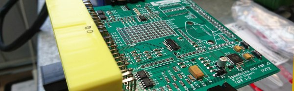
The modern internal combustion engine is an engineering marvel. We’re light-years ahead of simple big blocks and carburetors, and now there are very fast, very capable computers sensing adjusting the spark timing, monitoring the throttle position, and providing a specific amount of power to the wheels at any one time. For the last few years [Josh] has been building a fully-featured engine management system, and now he’s entered it in the Hackaday Prize.
The Speeduino project is, as the name would suggest, built around the Arduino platform. In this case, an Arduino Mega. The number of pins and PWMs is important — the Speeduino is capable of running the fuel and ignition for eight cylinder engines.
The Speeduino is designed to do everything an engine control unit can do, including rev limiting (although if you’re building your own ECU, why?), and reading ethanol sensors. Right now [Josh] is working on a beta run of the Speeduino designed for the 1.6L Miata. That’s an excellent platform for firmware performance tuning, and there’s still a lot of work to be done on the firmware side of things before everything’s all set to go. Still, this is a great project and sure to impress the bros at track day, bro.
As ever, I am fighting a marginally winning battle against my 1991 Mazda MX-5, and this is the story of how I came to install a wideband oxygen sensor in my Japanese thoroughbred. It came about as part of my ongoing project to build myself a viable racecar, and to figure out why my 1990s Japanese economy car engine runs more like a late 1970s Malaise-era boat anchor.
I’ve always considered myself unlucky. My taste for early 90s metal has meant I’ve never known the loving embrace of OBD-2 diagnostics, and I’ve had to make to do with whatever hokey system was implemented by manufacturers who were just starting to produce reliable fuel injection systems.
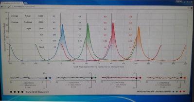
Narrowband oxygen sensor voltage output. The output is heavily dependent on sensor temperature and highly non-linear, making these sensors unsuitable for delivering a true AFR reading.
This generally involves putting in a wire jumper somewhere, attaching an LED, and watching it flash out the trouble codes. My Mazda was no exception, and after putting up with a car that was running rich enough to leave soot all over the rear bumper, I had to run the diagnostic.
It turned up three codes – one for the cam angle sensor, and two for the oxygen sensor. Now, a cam angle sensor (CAS) fault will normally prevent the car running at all, so it’s safe to assume that was an intermittent fault to keep an eye on.
The oxygen sensor, however, was clearly in need of attention. Its job is to allow the engine control unit (ECU) to monitor the fuel mixture in the exhaust, and make sure it’s not too rich or too lean. As my car was very obviously running too rich, and the diagnostic codes indicated an oxygen sensor failure, a repair was in order.
I priced up replacement sensors, and a new oxygen sensor could be had for under $100. However, it wasn’t exactly what I wanted, as not all oxygen sensors are created equal. Cars in the 80s and 90s typically shipped from the OEM fitted with what’s called a narrowband oxygen sensor. These almost always consist of a zirconia dioxide cell that outputs a voltage depending on the difference in oxygen concentration between the exhaust gas and the free air. These sensors generally sit at 0.45 V when the fuel mixture is stoichiometric, but rapidly change to 0.1 V in a lean condition and 0.9 V in a rich condition. The response is highly non-linear, and changes greatly with respect to temperature, and thus is only good for telling the ECU if it’s rich or lean, but not by how much. ECUs with narrowband sensors tend to hunt a lot when running in closed loop O2 control – you’ll see an engine at idle hunt either side of the magical 14.7 stoichiometric air fuel ratio, never able to quite dial in on the correct number.
As I intend to switch to an aftermarket ECU in the future, I’ll need to tune the car. This involves making sure the air/fuel ratios (AFRs) are correct, and for that I need to be able to properly measure them. Just knowing whether you’re rich or lean isn’t enough, as often it’s desirable to run the engine intentionally rich or lean at certain engine loads. To get a true AFR reading requires fitting a wideband oxygen sensor. These are a little more complicated.
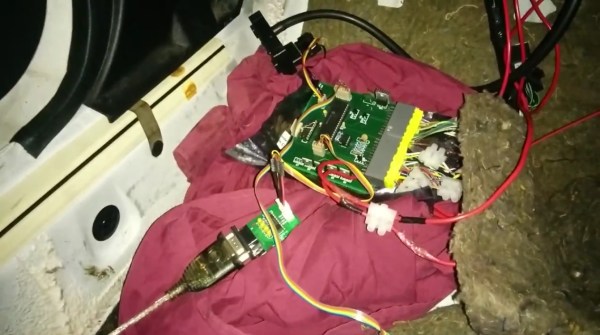
A big problem with most modern cars is the sheer number of parts and systems that are not user serviceable. This is a big departure from cars of just decades ago that were designed to be easily worked on by the owner. To that end, [Anthony] aka [fuzzymonkey] has tackled what is normally the hardest thing to work on in modern cars: the Engine Control Unit. (Older posts on this project can be found at [Anthony]’s old project log.)
Every sensor in any modern car is monitored by a computer called the Engine Control Unit (ECU), and the computer is responsible for taking this data and making decisions on how the car should be running. In theory a custom ECU would be able to change any behavior of the car, but in practice this is extremely difficult due to the sheer number of operations required by the computer and the very specific tolerances of a modern engine.
The custom ECU that Anthony has created for his Mazda MX-5 (a Miata for those in North America) is based on the PIC18F46K80 microcontroller, and there are actually two units involved. The first handles time-sensitive operations like monitoring the engine cam position and engine timing, and the other generates a clock signal for the main unit and also monitors things like cooling temperature and controlling idle speed. The two units communicate over SPI.
[Anthony]’s custom ECU is exceptional in that he’s gotten his car running pretty well. There are some kinks, but hopefully he’ll have a product that’s better than the factory ECU by allowing him to change anything from throttle response and engine timing to the air-fuel ratio. There have been a few other attempts to tame the ECU beast in the past, but so far there isn’t much out there.
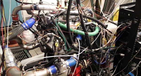
For his PhD at the University of Michigan, [Adam] designed a Raspberry Pi-based system that controls an HCCI engine, a type of engine which combines the merits of both diesel and gasoline engines. These engines exhibit near-chaotic behavior and are very challenging to model, so he developed a machine learning algorithm on a Raspberry Pi that adaptively learns how to control the engine.
[Adam]’s algorithm needs real-time readings of cylinder pressures and the crankshaft angle to run. To measure this data on a Raspberry Pi, [Adam] designed a daughterboard that takes readings from pressure sensors in each cylinder and measures the crankshaft angle with an encoder. The Pi is also equipped with a CAN transceiver that communicates with a low-level engine control unit.
[Adam]’s algorithm calculates engine control parameters in real-time on the Pi based on the pressure readings and crankshaft position. The control values are sent over CAN to the low-level engine controller. The Pi monitors changes in the engine’s performance with the new values, and makes changes to its control values to optimize the combustion cycle as the engine runs. The Pi also serves up a webpage with graphs of the crankshaft position and cylinder pressure that update in real-time to give some user feedback.
For all the juicy details, take a look at [Adam]’s paper we linked above. For a more visual breakdown, check out the video after the break where [Adam] walks you through his setup and the awesome lab he gets to work in.
Is there a place in the dashboard of your high performance automobile for this Engine Control Unit feedback panel? There’s several methods of showing information at work here. The row of LEDs at the top of the bezel provide RPM feedback. The two red LEDs with chrome bezels are alarm indicators. But that big OLED display is the centerpiece of the unit. Not only can you scroll through a myriad of display options, but the screen packs more than enough contrast to be readable during the day. It looks like [Mathieu] is selling these units and has decided not to release source code because of this, but there’s a schematic available and a video after the break shows the menu system from which you can draw inspiration.


 [Adam]’s algorithm calculates engine control parameters in real-time on the Pi based on the pressure readings and crankshaft position. The control values are sent over CAN to the low-level engine controller. The Pi monitors changes in the engine’s performance with the new values, and makes changes to its control values to optimize the combustion cycle as the engine runs. The Pi also serves up a webpage with graphs of the crankshaft position and cylinder pressure that update in real-time to give some user feedback.


