Extreme Espresso, Part 2: An Inductive Water Level Sensor

[Mark Smith] must really, really like his coffee, at least judging by how much effort he’s put into tricking out his espresso machine.

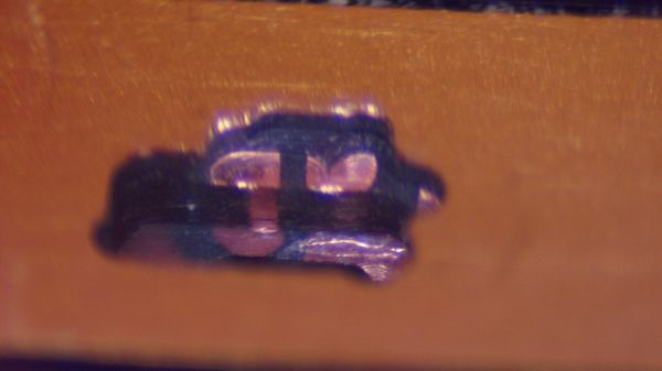
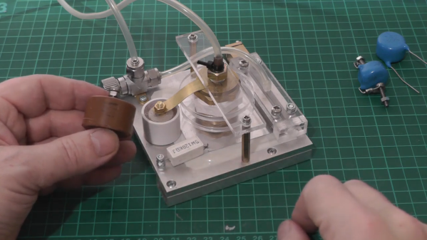
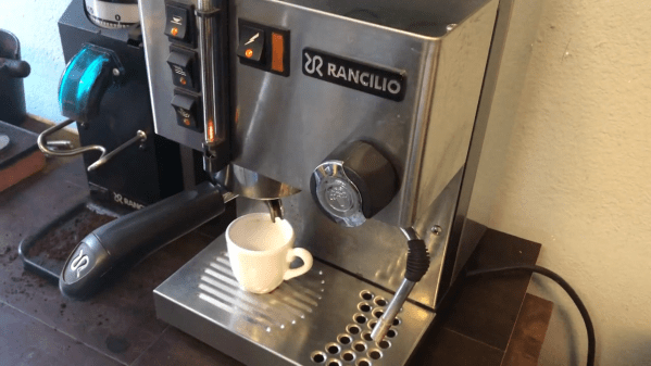
This inductive water tank sensor is part of a series of innovations [Mark] has added to his high-end Rancilio Silvia machine — we assume there are those that would quibble with that characterization, but 800 bucks is a lot to spend for a coffee maker in our books. We recently featured a host of mods he made to the machine as part of the “Espresso Connect” project, which includes a cool Nixie tube bar graph to indicate the water level in the machine. That display is driven by this sensor, the details of which [Mark] has now shared. The sensor straddles the wall of the 1.7-liter water tank, so no penetrations are needed. Inside the tanks is a track that guides a copper and PETG float that’s sealed with food-safe epoxy resin.

Directly adjacent to the float track on the outside of the tank is a long PCB with a couple of long, sinuous traces. These connect to an LX3302A inductive sensor IC, which reads the position of the copper slug inside the float. That simplifies the process greatly; [Mark] goes into great detail about the design and calibration of the sensor board, as well as hooking it into the Raspberry Pi Zero that lies at the heart of “Espresso Connect’. Altogether, the mods make for a precisely measured dose of espresso, as seen in the video below.

We’d say this was maybe a bit far to go for the perfect cup of coffee, but we sure respect the effort. And we think this inductive sensor method has a lot of non-caffeinated applications that probably bear exploration.

Continue reading “Extreme Espresso, Part 2: An Inductive Water Level Sensor”

PCB internal bodge

PCB Microsurgery Puts The Bodges Inside The Board

We all make mistakes, and there’s no shame in having to bodge a printed circuit board to fix a mistake. Most of us are content with cutting a trace or two with an Xacto or adding a bit of jumper wire to make the circuit work. Very few of us, however, will decide to literally do our bodges inside the PCB itself.

The story is that [Andrew Zonenberg] was asked to pitch in debugging some incredibly small PCBs for a prototype dev board that plugs directly into a USB jack. The six-layer boards are very dense, with a forest of blind vias. The Twitter thread details the debugging process, which ended up finding a blind via on layer two shorted to a power rail, and another via shorted to ground. It also has some beautiful shots of [Andrew]’s “mechanical tomography” method of visualizing layers by slowly grinding down the surface of the board.

[Andrew] has only tackled one of the bodges at the time of writing, but it has to be seen to be believed. It started with milling away the PCB to get access to the blind via using a ridiculously small end mill. The cavity [Andrew] milled ended up being only about 480 μm by 600 μm and only went partially through a 0.8-mm thick board, but it was enough to resolve the internal short and add an internal bodge to fix a trace that was damaged during milling. The cavity was then filled up with epoxy resin to stabilize the repair.

This kind of debugging and repair skill just boggles the mind. It reminds us a bit of these internal chip-soldering repairs, but taken to another level entirely. We can’t wait to see what the second repair looks like, and whether the prototype for this dev board can be salvaged.

Thanks to [esclear] for the heads up on this one.

Epoxy lenses

The Ins And Outs Of Casting Lenses From Epoxy

If you need a lens for a project, chances are pretty good that you pick up a catalog or look up an optics vendor online and just order something. Practical, no doubt, but pretty unsporting, especially when it’s possible to cast custom lenses at home using silicone molds and epoxy resins.

Possible, but not exactly easy, as [Zachary Tong] relates. His journey into custom DIY optics began while looking for ways to make copies of existing mirrors using carbon fiber and resin, using the technique of replication molding. While playing with that, he realized that an inexpensive glass or plastic lens could stand in for the precision-machined metal mandrel which is usually used in this technique. Pretty soon he was using silicone rubber to make two-piece, high-quality molds of lenses, good enough to try a few casting shots with epoxy resin. [Zach] ran into a few problems along the way, like proper resin selection, temperature control, mold release agent compatibility, and even dealing with shrinkage in both the mold material and the resin. But he’s had some pretty good results, which he shares in the video below.

[Zach] is clear that this isn’t really a tutorial, but rather a summary of the highs and lows he experienced while he was working on these casting methods. It’s not his first time casting lenses, of course, and we doubt it’ll be his last — something tells us he won’t be able to resist trying this all-liquid lens casting method in his lab.

Continue reading “The Ins And Outs Of Casting Lenses From Epoxy”

Flat Transformer Gives This PCB Tesla Coil Some Kick

Arguably, the most tedious part of any Tesla coil build is winding the transformer. Getting that fine wire wound onto a suitable form, making everything neat, and making sure it’s electrically and mechanically sound can be tricky, and it’s a make-or-break proposition, both in terms of the function and the aesthetics of the final product. So this high-output printed circuit Tesla should take away some of that tedium and uncertainty.

Now, PCB coils are nothing new — we’ve seen plenty of examples used for everything from motors to speakers. We’ve even seen a few PCB Tesla coils, but as [Ray Ring] points out, these have mostly been lower-output coils that fail to bring the heat, as it were. His printed coil generates some pretty serious streamers — a foot long (30 cm) in some cases. The secondary of the coil has 6-mil traces spaced 6 mils apart, for a total of 240 turns. The primary is a single 240-mil trace on the other side of the board, and the whole thing is potted in a clear, two-part epoxy resin to prevent arcing. Driven by the non-resonant half-bridge driver living on the PCB below it, the coil can really pack a punch. A complete schematic and build info can be found in the link above, while the video below shows off just what it can do.

Honestly, for the amount of work the PCB coil saves, we’re tempted to give this a try. It might not have the classic good looks of a hand-wound coil, but it certainly gets the job done. Continue reading “Flat Transformer Gives This PCB Tesla Coil Some Kick”

Faux Stained Glass Effect, With 3D Printing And Epoxy

Like the looks of stained glass, but not the amount of work, skill, and materials involved? Well, [Northern Geometry] shows how to sidestep all that nonsense and use a 3D printed frame, epoxy, and some alcohol-based inks to create a pretty good fake stained-glass effect piece of art.

A smooth polypropylene board is the key to a glassy smooth back.

[Northern Geometry] has played with this idea before, but shares some refinements and tips on getting the best results. One suggestion is to begin by securely taping the 3D printed frame to a smooth polypropylene board as a backer. Giving the cured resin a smooth surface is important to get the right look, and since resin will not bond to the polypropylene, it can be used as a backer to get that done.

Once the frame is mounted, pour a small amount of epoxy into each cavity and ensure it gets into every corner, then let it cure. The thin bottom layer of resin will seal things as well as create a glassy-smooth backing that is the perfect foundation for finishing the piece with colored resin as needed.

Once that is done, and everything has had plenty of time to cure fully, just pop the piece off the board. Check it out in the video embedded below, where [Northern Geometry] shows the process from start to finish.

Continue reading “Faux Stained Glass Effect, With 3D Printing And Epoxy”

3D-Printed Press-Forming Tools Dos And Don’ts

Press-forming is a versatile metal forming technique that can quickly and easily turn sheet metal into finished parts. But there’s a lot of time and money tied up in the tooling needed, which can make it hard for the home-gamer to get into. Unless you 3D-print your press-form tooling, of course.

Observant readers will no doubt recall our previous coverage of press-forming attempts with plastic tooling, which were met with varying degrees of success. But [Dave]’s effort stands apart for a number of reasons, not least of which is his relative newbishness when it comes to hot-squirt manufacturing. Even so, he still came up with an interesting gradient infill technique that put most of the plastic at the working face of the dies. That kept print times in the reasonable range, at least compared to the days of printing that would have been needed for 100% infill through the whole tool profile.

The other innovation that we liked was the idea to use epoxy resin to reinforce the tools. Filling the infill spaces on the tools’ undersides with resin resulted in a solid, strong block that was better able to withstand pressing forces. [Dave] didn’t fully account for the exothermic natures of the polymerization reaction, though, and slightly warped the tools. But as the video below shows, even suboptimal tools can perform, bending everything he threw at them, including the hydraulic press to some extent.

It sure seems like this is one technique to keep in mind for a rainy day. And hats off to [Dave] for sharing what didn’t work, since it points the way to improvements.

Continue reading “3D-Printed Press-Forming Tools Dos And Don’ts”

Homebrew Doorknob Caps For High-Voltage Fun

Mouser and Digi-Key are great for servicing most needs, and the range of parts they offer is frankly bewildering. But given the breadth of the hardware hacking community’s interests, few companies could afford to be the answer to everyone’s needs.

That’s especially true for the esoteric parts needed when one’s hobby involves high voltages and homemade lasers, like [Les Wright]. He recently came up with a DIY doorknob capacitor design that makes the hard-to-source high-voltage caps much easier to obtain. We’ve seen [Les] use these caps in his transversely excited atmospheric (TEA) lasers, a simple design that uses high-voltage discharge across a long, narrow channel filled with either room air or nitrogen. The big ceramic caps are needed for the HV supply, and while [Les] has a bunch, they’re hard to come by online. He tried a follow-up using plain radial-lead ceramic capacitors, and while the laser worked, he did get some flashover between the capacitor leads.

[Les]’s solution was to dunk the chunky caps in acetone for a week or so to remove their epoxy covering. Once denuded, the leads were bent into a more axial configuration and soldered to brass machine screws. The dielectric slug is then put in a small section of plastic tubing and potted in epoxy resin with the bolts protruding from each end. The result is hard to distinguish from a genuine doorknob cap; the video below shows the build process as well as some testing.

Hats off to [Les] for taking pity on those of us who want to replicate his work but find ourselves without these essentials. It’s nice to know there’s a way to make unobtanium parts when you need them.

Continue reading “Homebrew Doorknob Caps For High-Voltage Fun”