Got a bunch of questionable electrolytic caps sitting in your junk bin? Looking to recap a vintage radio chassis? Then you might need to measure the equivalent series resistance of the capacitors, in which case this simple five-transistor ESR meter might come in handy.
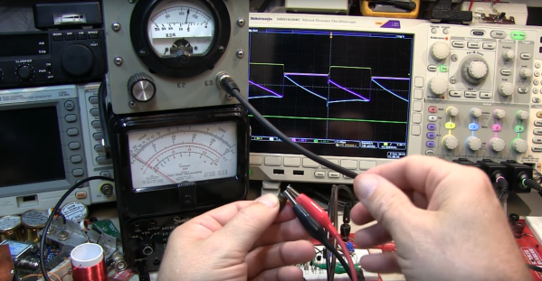
Even if you have no need for an ESR meter, [W2AEW]’s video below is a solid introduction to how ESR is determined. The circuit itself comes from EEVBlog forum user [Jay-Diddy_B] and is about as simple as such a circuit can get. Two transistors form an oscillator that generates a square wave that drives a resistor bridge network. The two legs of the bridge feed matched common-emitter amps, one leg through the device under test. The difference in voltage between the two legs is read on a meter, and you have a quick and simple way to sort through the caps in your junk bin. [Jay-Diddy_B]’s circuit is only presented in breadboard form; no attempt was made to field a practical instrument. Indeed, [W2AEW] already built a home-brew ESR meter using hex inverters and op amps to which he compares the five-transistor circuit’s results. His intention here seems to be to clarify the technique of ESR measurement and evaluate an even simpler circuit than his. We think he’s done a good job on both counts.
We’ve featured plenty of [WA2AEW]’s work before, like this Michigan Mity-Mite transmitter or his primer on oscilloscopes. We really like his laid back style and the way he makes complex topics easy to understand. Check them out.
Continue reading “Getting A Handle On ESR With A Couple Of DIY Meters”


