Baby Steps Toward DIY Autonomous Driving: VW Golf Edition

Nice thermal design, but conformal coating and no ID marks make this tough to reverse engineer

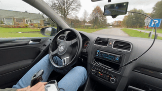
[Willem Melching] owns a 2010 Volkswagen Golf – a very common vehicle in Europe – and noticed that whilst the electronic steering rack supports the usual Lane Keep Assist (LKAS) system, and would be theoretically capable of operating in a far more advanced configuration using openpilot, there were some shortcomings in VW’s implementation which means that it would not function for long enough to make it viable. Being very interested in and clearly extremely capable at reverse engineering car ECUs and hacking them into submission, [Willem] set about documenting his journey to unlocking openpilot support for his own vehicle.

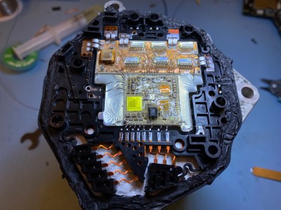
And what a journey it was! The four-part blog series is beautifully written, showing every gory detail and all tools used along the way. The first part shows the Electronic Power Steering (EPS) ECU from a 2010 Volkswagen Golf Mk6 module (which rides on the back of the three-phase steering rack motor) being cracked open to reveal an interesting multi-chip module approach, with bare die directly bonded to a pair of substrate PCBs, that are in turn, bonded to the back of the motor casing, presumably for heat dissipation reasons. Clever design, but frustrating at the same time as this makes part identification somewhat tricker!

Entropy less the 1.0, and zero sections indicate no encryption applied

[Willem] uses a variety of tools and tricks to power up and sniff the ECU traffic on the CAN bus, when hooked up to a SAE J2534-compliant debug tool, eventually determining it speaks the VW-specific TP2.0 CAN bus protocol, and managed to grab enough traffic to check that it was possible to use the standard KWP2000 diagnostic protocol to access some interesting data. Next was a very deep dive into reverse engineering update images found online, by first making some trivial XOR operations, then looking at an entropy plot of the file using Binwalk to determine if he really did have code, and if it was encrypted or not, After running cpu_rec, it was determined the CPU was a Renesas V850. Then the real work started – loading the image into Ghidra to start making some guesses of the architecture of the code, to work out what needed patching to make the desired changes. In the final part of the series, [Willem] extracts and uses the bootloader procedure to partially patch the code configuration area of his vehicle and unlocks the goal he was aiming at – remote control of his steering. (OK, the real goal was running openpilot.)

In our opinion, this is a very interesting, if long, read showing a fascinating subject expertly executed. But we do want to stress, that the vehicular EPS module is an ASIL-D safety tested device, so any hacks you do to a road-going vehicle will most definitely void your insurance (not to mention your warranty) if discovered in the event of a claim.

Older ECUs are a bit easier to hack, if you can pull the EPROM, and people out there are producing modules for allsorts of vehicular hacking. So plenty to tinker with!

3D Printering: Adding A Web Interface Where There Was None Before

[Renzo Mischianti] got himself a Chinese 3D printer, specifically a FlyingBear Ghost 5. (Cracking name, huh?) He was more than a little irritated with the fact that whilst the controller, an MKS Robin Nano, did have a integrated Wi-FI module, it provided no browser-based interface for monitoring and control purposes. This seemed a bit short-sighted in this day and age, to say the least. Not being at all happy with that situation, [Renzo] proceeded to write dedicated Wi-Fi firmware using websockets, but not without fully documenting his journey in a detailed series of the blog posts.

The resulting BeePrint web interface supports all the usual functions you would expect when managing a printer, everything from monitoring warm-up at the prep stage, to keeping tabs on the potential spaghetti monster via the connected IP camera. All good stuff. [Renzo] used an ESP32-cam, which is a low-cost 2 MP unit from our friends at Olimex, but we suspect it wouldn’t vastly difficult to add your own IP camera into the mix.

[Renzo] has a YT channel detailing quite a few other projects, which is definitely worth some viewing time in our opinion.

We’ve been covering 3D printer hacking since the dinosaurs were roaming. This is the oldest, and still one of the strangest, posts that we could find in a quick search. Anyone care to find something older?

Continue reading “3D Printering: Adding A Web Interface Where There Was None Before”

M5Paper Gets Open Source Weather Display Firmware

We know you like soldering irons, we’re quite fond of them ourselves. But the reality is, modular components and highly capable development boards allow the modern hardware hacker to get things done with far less solder smoke then ever before. In fact, sometimes all you need to finish your project is the right code.

Case in point, check out the slick electronic paper weather display that [Danko Bertović] shows off in the latest Volos Projects video. While it certainly fits the description of a DIY project, he didn’t have to put any of the hardware together himself. The M5Paper is an ESP32 development kit designed around a crisp 4.7″, 960 x 540 e-paper panel that includes everything from environmental sensors to an internal 1150 mAh battery. To make your handheld e-paper dreams come true, the only thing you need to provide is the software.

The weather display code provided by [Danko] should certainly get you going in the right direction. Now don’t get us wrong, there’s certainly no shame in just flashing his code to the device and plunking it on your desk. It’s a gorgeous looking interface, and we all know that a sprinkling of open source code is often all it takes to make a standard consumer device extraordinary. But by using the code he’s provided as a launching point, you can take this turn-key device and really make it your own.

Continue reading “M5Paper Gets Open Source Weather Display Firmware”

A Nokia 5110 playing a game

Firmware Modding Your Vintage Nokia Handset

These days we’re spoiled for choice when it comes to smartphone software, especially games. Official repositories for the leading handsets feature hundreds of thousands of games, and sideloading adds infinite possibilities. If you were lucky enough to be sporting a Nokia handset in the late 1990s, you probably had all of three games to choose from (and only one that was actually fun). [Janus Cycle] explores the steps needed to firmware mod your vintage Nokia phone, and how to expand on that paltry games library.

Enthusiasts have been modding their Nokia handsets since the 2000s, and the tools required now are the same as they were then. The Nokia 5110 and 6110 (as featured in the video below) use a proprietary cable and connector for communicating with PCs and other devices. Nokia’s official serial cable already opens up many possibilities for handset tinkering, including access to RAM and toggling Monitor Mode. This cable interfaces solely with the phone’s fast FBUS protocol, however firmware flashing takes place using the slower MBUS protocol over a single wire bi-directional pin.

The handset expects both serial ports to be available during firmware flashing. [Janus Cycle] demonstrates how to build a custom harness that connects both serial ports to a PC parallel port. At this point the flashing process is relatively straightforward, especially if you have an appropriately vintage computer to run the old flashing software.

Nokia owners may fondly remember changing the network name on the home screen to all sorts of inappropriate graphics, yet far more was possible with the right technology and know-how. It’s interesting to think about what may have been if softmodding was more widespread during the reign of the Nokia 5110 and its peers.

Continue reading “Firmware Modding Your Vintage Nokia Handset”

Streaming Video From A Mouse

The first optical mice had to be used on a specially printed mousepad with a printed grid that the four-quadrant infrared sensor could detect. Later, mice swapped the infrared sensor for an optoelectric module (essentially a tiny, very low-resolution camera) and a powerful image processing. [8051enthusiast] was lying in bed one day when they decided to crack the firmware in their gaming mouse and eventually start streaming frames from the camera inside.

Step one was to analyze the protocol between the mouse and the host machine. Booting up a Windows VM and Wireshark allowed him to capture all the control transfers to the USB controller. Since it was a “programmable” gaming mouse that allowed a user to set macros, [8051enthusiast] could use the control transfers that would normally query that macro that had been set to return the memory at an arbitrary location. A little bit of tinkering later, and he now had a dump of the firmware. Looking at the most abundant bytes, it seems to match a profile similar to the Intel 8051. In a fascinating blur of reverse engineering, he traced the main structure of the program back from the function that sets the LED colors for the scroll wheel (which is dependent on the current DPI setting). Unfortunately, the firmware prevented the same macro mechanism from writing to arbitrary locations.

Looking through the code, a good old buffer overflow exploit seemed possible, but it caused the system to reset via watchdog. So he took another approach, invoking recovery mode and loading an entirely new firmware on the device, which a set_report control transfer can invoke.

Next, he moved onto the ADNS-9800 optical sensor (pictured in the top image provided by JACK Enterprises), which had a large encrypted blob in the firmware. Some poking around and deduction lead to a guess that the optical sensor was another 8051 system. With some clever reasoning and sheer determination, [8051enthusiast] was able to crack the XOR stream cipher encryption with a program that showed him versions of the disassembled assembly and allowed him to pick the one that was the most likely. With the firmware decrypted, he was able to see the encryption code and confirm his deducted algorithm.

With the sensor now cracked open, it was onto the 30 x 30 240 fps video stream. The sensor communicates over SPI, and the USB controller has to bit-bang the connection as it doesn’t have the hardware. Putting two custom firmware images on with a few extra functions was easy enough, but the 7 fps was somewhat lacking. The first optimization was loop unrolling and removing some sleeps in the firmware, which bought it up to 34 fps. By measuring the cycle counts of individual instructions, he was able to find some alternatives such as a mov instead of a setb that took one less cycle. Going from a 17 cycle loop to an 11 cycle loop and some other optimizations gave him 54 fps. Not content to stop there, he modified the ADNS-9800 firmware to continuously sample rather than waiting for the USB controller to finish processing. While this yielded 100 fps, there was still more to do: image compression. At a whopping 230 fps, [8051enthusiast] decided to call it done.

However, there was one last thing he wanted to do: control the mouse with the video stream. Writing some image processing into his Python-based program that received the image files allowed him to use the mouse, however impractically.

All in all, it’s an incredible journey by [8051enthusiast], and we would highly recommend reading the whole journey yourself. This isn’t the first time he’s modified the firmware of 8051-based devices, such as modifying the firmware of the WiFi chipset in his laptop.

[Thanks to JACK Enterprises over at Tindie for the use of the image of an ADNS9000].


Extracting The WiFi Firmware And Putting Back A Keylogger

In the interest of simplification or abstraction, we like to think of the laptop on the kitchen table as a single discrete unit of processing. In fact, there is a surprisingly large number of small processors alongside the many cores that make up the processor. [8051enthusiast] dove into the Realtek rtl8821ae WiFi chip on his laptop and extracted the firmware. The Realtek rtl8821ae chip is a fairly standard Realtek chip as seen in this unboxing (which is where the main image comes from).

True to his name, [8051enthusiast] was pleased to find that the rtl8821ae was clearly based on the Intel 8051. The firmware was loaded on startup from a known file path and loaded onto the chip sitting in an M.2 slot. Careful consideration, [8051enthusiast] reasoned that the firmware was using RTX51 Tiny, which is a small real-time kernel.

The firmware is loaded at 0x4000 but it calls to code below that address, which means there is a ROM on the chip that contains some code. The easiest way to extract it would be to write some custom code that just copies the masked ROM back to the main CPU via the shared memory-mapped config space, but the firmware is checksummed by the masked ROM code. However, the checksum is just a 16-bit XOR. With a tweak in the kernel to allow accessing the shared config space from userspace, [8051enthusiast] was on his way to a complete firmware image.

Next, [8051enthusiast] looked at what could be done with his newfound hackability. The keyboard matrix is read by the Embedded Controller (EC), which happens to be another 8051 based microcontroller. There also happens to be an RX and a TX trace from the EC to the m.2 slot (where the rtl8821ae is). This has to do with 0x80 postcodes from the processor being routed out somewhere accessible via the EC. With a bit of custom code on both the EC and the WiFi chip, [8051enthusiast] had a keylogger that didn’t run on the main processor broadcasting the PS/2 keystrokes as UDP packets.

Of course, there are plenty of other 8051 based devices out there just waiting to be discovered. Like this 8051 based e-ink display controller.

[Main image source: Realtek RTL8821AE unboxing on YouTube by Евгений Горохов]

Commodore Inspired Watch Puts BASIC On Your Wrist

Ask a smart watch owner what their favorite wrist-mounted feature is, and they might say it’s having all their daily information available at a glance, or the ease with which they’re able to communicate with friends and family. If they don’t mention knocking out a few lines in their wearable BASIC interpreter, then you know you aren’t talking to [Nick Bild]. His “C64 Watch” firmware for the LILYGO T-Watch 2020 not only takes some visual inspiration from the Commodore 64, but also lets you relive those early computing glory days with a functional BASIC environment.

Originally [Nick] used a teeny tiny onscreen keyboard to tap out his BASIC programs, but finding the experience to be uncomfortably like torture, he switched over to using USB. Just plug the watch into your computer, open your favorite serial terminal, and you’ll have access to the customized version of TinyBasic Plus running on the watch. To make things  even easier, he’s looking at implementing a web-based terminal over WiFi so you don’t need to plug the watch in.

When you aren’t running BASIC you’ll be treated to a Commodore-themed watch face, complete with the classic READY. prompt. A small battery indicator is hidden up in the top-right corner, and tapping on the rainbow colored “C” will launch the menu. It’s pretty simplistic, but of course what else would you expect given the source material?

Looking ahead, [Nick] says he’d also like to implement a C64 emulator into the firmware so the watch could run original software. We’re a bit skeptical about how practical that would actually be, but we’ll reserve judgement until we see it in operation. He’s also hoping other Commodore aficionados will chime in with their own improvements and new features for the watch.

You might think that a Commodore 64 emulator on your wrist would be the most outlandish way to run your old games and software, but we’d say playing Turrican in a virtual reality microcosm of the 1980s takes the cake.

Continue reading “Commodore Inspired Watch Puts BASIC On Your Wrist”