We’d Sure Like To Strum The Chrumm Keyboard

If you want something as personal as a keyboard done right, you have to do it yourself. Not quite satisfied with the multitude of mechanical offerings out there, [summific] decided to throw their hat into the ring and design the Chrumm keyboard. And boy, are we glad they did.

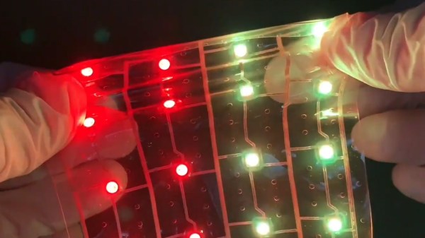
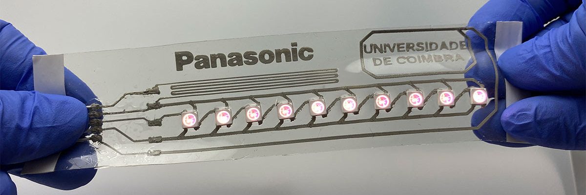
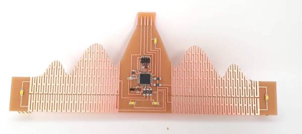
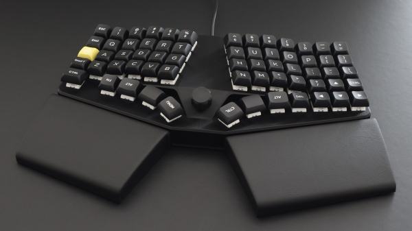
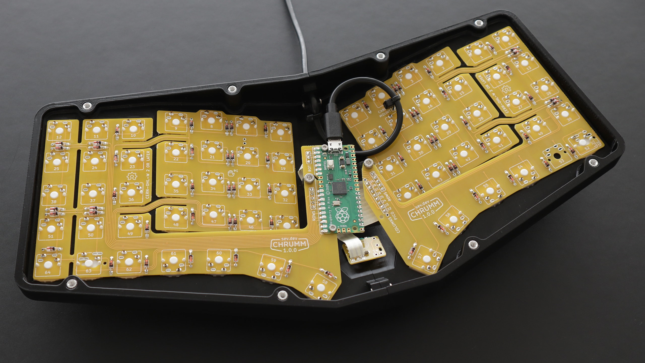
Between the lovely tenting angle and tilt, the gorgeous flexible PCBs, and the pictures that could pass for renders, [summific] has given us something beautiful to behold that we can only dream of thocking on. Even the honeycomb plate is nice. Oh, but this monoblock split is completely open source.

This Raspberry Pi Pico-powered keyboard features a 3D printable case design without visible screws, and a rotary encoder in the middle. Those palm rests are firmly attached from the underside. Why are the thumb cluster keycaps upside down? It’s not meant to drive you insane; it’s because the contour is more finger-friendly that way, according to some people.

[summific] makes this look easy, but it doesn’t matter, because all the hard work is already done. If you want something easier, start with a macropad. Or a macro pad, even.

Via reddit

a flexible film with a matrix of illuminated color LEDs being stretched

Truly Flexible Circuits Are A Bit Of A Stretch

Flexible PCBs have become increasingly common in both commercial devices and DIY projects, but Panasonic’s new stretchable, clear substrate for electrical circuits called Beyolex takes things a step further. The material is superior to existing stretchable films like silicone, TPU, or PDMS due to its high heat tolerance (over 160° C) for the purposes of sintering printable circuit traces.

But, a flexible substrate isn’t very useful for electronics without some conductive traces. Copper and silver inks make for good electrical circuits on stretchable films, and are even solderable, but increase resistance each time they are stretched. Recently, a team out of the University of Coimbra in Portugal has developed a liquid metal ink that can stretch without the resistance issues of existing inks, making it a promising pair with Panasonic’s substrate. There’s also certain environmental benefits of printing circuits in this manner over traditional etching and even milling, as you’re only putting conductive materials where needed.

a flexible film with a strip of LEDs connected by a novel liquid metal ink circuit

After the break, check out Panasonic’s earlier videos showing some of their demo circuits that include a stretchable NFC antenna harvesting electricity even while submerged in water and an LED matrix performing while being, bent, rolled, and stretched. We’re excited to see where this technology leads and when we hackers will be able to create our own stretchable projects.

A great many flexible PCB projects have graced Hackaday, from early experiments to sophisticated flexible PCB projects. Heck, we had a whole Flexible PCB Contest with some awesome flexible projects.

Continue reading “Truly Flexible Circuits Are A Bit Of A Stretch”

A display based on magnetic viewing film

Moving Magnet Draws Stylish Shapes On Flexible Film

[Moritz v. Sivers] has a knack for making his own displays, which are typically based on some obscure physical effect. Magnetic viewing films, those thin plastic sheets that change color in response to a magnetic field, are his latest area of interest, as you can see in his Magnetic Kinetic Art Display.

The overall idea of the display is similar to a kinetic sand art table, in which a ball traces out shapes in a pile of sand. In [Moritz]’s project, the magnetic viewing film is the sand, and a 2 mm diameter magnet is the ball. The magnet is moved along the film by two sets of coils embedded inside a flex PCB mounted just below the film. One set of coils, on the top layer of the PCB, moves the magnet in the x direction, while a second set on the bottom layer moves it in the y direction.

A flex PCB with coils on both sides
The flex PCB is small, but carries lots of windings

[Moritz] used a flex PCB not because it had to be bendy, but to keep the two sets of coils as close together in the z direction as possible. This helps to avoid a big difference in strength between the two directions. To drive the coils, he used a pair of TB6612FNG stepper motor drivers, controlled by a Wemos D1 Mini.

The housing was 3D printed mostly from PLA, but with a few bits done in PETG. This was for structural rigidity as well as thermal performance — the coils can carry up to two amps and get pretty warm as a result.

The video, embedded below, shows some of the shapes that can be drawn: squares, spirals and even digits to turn the display into a clock. [Moritz] got the PCB coil idea from a project by [bobricius], and cleverly extended it into a useful product. It’s not the first time [Moritz] used magnetic viewing film to make a clock, either.

Continue reading “Moving Magnet Draws Stylish Shapes On Flexible Film”

A crown ornament made from PCB material

Clever Design Technique Makes Flexible PCB Fit For A Queen

Printed circuit boards can be square, round, octagonal, or whatever shape you desire. But there’s little choice when it comes to the third dimension: most PCBs are flat and rigid. Sure, you can make flexible PCBs like the kapton-backed ones you find inside electronic gadgets, but those are complicated to work with. As it turns out however, you can also make flexible boards using regular PCB material: check out [Rehana Al-Soltane]’s Flexible Crown PCB, a project she did as part of [Neil Gershenfeld]’s “How To Make (Almost) Anything” class at MIT.

The basic idea is to create flexures in the PCB by milling out several long slots with thin pieces connecting the two sides. [Rehana] got this idea from [Quentin Bolsée]’s flexible capacitive sensor project and applied it to make a crown-shaped PCB with sparkly LEDs. The crown can bend through 180 degrees and can actually be worn as a head ornament, with pin headers to clamp it down on the wearer’s hair.

[Rehana] used a tool called svg-pcb to design the board. This is an open source toolkit that lets you design PCBs by describing them in code, rather than drawing shapes by hand. Although this might look a bit odd if you’re used to working with traditional PCB design software, it’s ideal for making repetitive structures like the flexures in the crown: simply write a for loop and let the tool generate a perfect array of identical slots.

Fabricating the Flexible Crown posed a few difficulties of its own, because the PCB began to flex and wiggle itself loose before the milling process was finished. As it turned out, the trick was to cut all the slots on the interior first and only mill the board’s outline as the very last step.

Adding flexures to a PCB like this looks like a promising technique and we’ll keep an eye on further developments in this field. There are other ways of making bendy boards though: researchers at the University of Maryland used a laser engraver to make foldable PCBs. Our 2019 Flexible PCB Contest also yielded several impressive implementations.

Continue reading “Clever Design Technique Makes Flexible PCB Fit For A Queen”

Fiber Laser Your Way To Flexible PCB Success!

It’s not often we feel that something we’re featuring is a genuinely new and groundbreaking technique, but a team from the University of Maryland’s Small Artifacts Lab may have done just that with their foldable and flexible PCBs created using a fiber laser engraver.

Laser engraving a PCB is nothing new, but they’ve taken a custom PCB material made using Kapton tape and copper foil, and fine-tuned the engraver to not only selectively remove copper, but also to create in-place folds in the Kapton substrate. They have even used the laser to melt solder paste and solder components, though we’re not so convinced about the quality as seen in the video below the break. This means that they can not only create 3-dimensional PCB sculptures but also useful structures such as their example of an all-PCB micro switch. To make things easy they’ve even created a custom CAD package for designing in this medium.

Perhaps best of all, there appears to be nothing here that couldn’t be also performed outside the lab by anyone with enough Kapton and copper, and a fiber laser. We’re looking forward to where this technique will go. If you’re interested, you can read their paper here.

Continue reading “Fiber Laser Your Way To Flexible PCB Success!”

Flapping PCB Fan Blows A Little Bit

Moving air with spinning blades is the most popular way, but it is not the only way. Using the PCB actuator technology he has been working on for the past few years, [Carl Bugeja] built a small electromagnetic flapping fan using a custom flexible PCB.

Inspired by expensive piezoelectric fans ($400 for a 30mW fan), [Carl] wanted to see if a cheaper alternative could be made. Using a similar design to his other PCB actuators, he had a custom flexible PCB made with an integrated coil, which can flex on two thin supports. These supports also contain the power traces for the coil. By sticking the base of the PCB between two neodymium magnets, it can flap back and forth when driven by an alternating current. It produces a bit of airflow, but nearly enough to be useful. The power traces in the thin supports also break after an extended period of 180° flapping.

Although this probably won’t be a viable replacement for a rotary fan, it would be interesting to see how far one can push this approach by optimizing the design and magnet arrangement.

Continue reading “Flapping PCB Fan Blows A Little Bit”

When [Carl] Says Jump, PCBs Say “How High?”

We’ve noticed that [Carl Bugeja] likes flexible PCBs. His latest exploit is to make PCB-based springs that combine with some magnets to create little devices that jump. We aren’t sure what practical use these might have, but they are undeniably novel and you can see them — um — jumping around, in the video, below.

[Carl] did many experiments with the spring construction and design. You can see several of the iterations in the video, not all of which worked out well. A PCB coil in the base becomes magnetized when current flows and this repels or attracts the magnets at the other end of the spring. What can you do with a PCB spring? We aren’t sure. Maybe this is how your next microrobot could climb stairs?

Adding stiffeners produced springs too stiff for the electromagnet to attract. We wondered if a different coil design at the base might be more effective. For that matter, you might not have to use a flat PCB coil in that position if you were really wanting to optimize the jumping behavior.

Usually, when we are checking in with [Carl] he is making PCB-based motors. Or, sometimes, he’s making PCB heaters for reflow soldering. We’ve seen jumping robots, before, of course. we will say the magnets seem less intense than using compressed air.

Continue reading “When [Carl] Says Jump, PCBs Say “How High?””