[Conor Patrick] is no stranger to hardware development, and he’s had an interesting project for the past few months. He’s attempting to create a tool to convert images of technical drawings (such as footprints for electronic components) into digital formats that can be imported into other tools. This could automate turning a typical footprint drawing like the one shown into an actual part definition in a CAD program, which could really speed up the creation of custom parts.
Key to the entire concept is the detection of lines in a black-and-white technical drawing. To some people this won’t sound like a particularly challenging problem; choose one or another baked-in line detection function, maybe with a bit of pre or post-processing, and that should be that. It turns out that detecting lines can be harder than expected, and as usual the devil is in the detail.
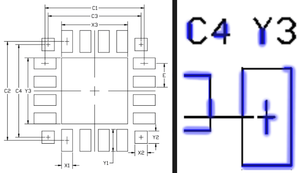
When [Conor] tried some existing methods for detecting lines, the results appeared good at first but came up short in frustrating ways. Software did not appreciate that in a technical drawing, a line is a single unbroken unit from point A to point B. Without that assumption, what should be a single line sometimes had sections missing, or single lines were detected as multiple segments instead of a unit. Lines that crossed other lines complicated things. Unwanted lines like a “1” or the lower half of a “Y” were being detected. There had to be a better way.
In the end, a custom solution that took proper advantage of the nature of the source images and made the correct assumptions is what made all the difference. With some intelligent threshold setting combined with looking at vertical and horizontal line instances separately, it was possible to locate lines and their lengths far more accurately than any other method he had tried. The system doesn’t handle sloped lines yet, but it might be possible to simply iterate through rotations of the image while applying the same method. If you have a better solution, [Conor] wants to hear from you.
Of course, garbage in means garbage out and sadly not all technical drawings measure up.