Exploring Woodworking Mysteries With Strain Gauges And Raspberry Pi

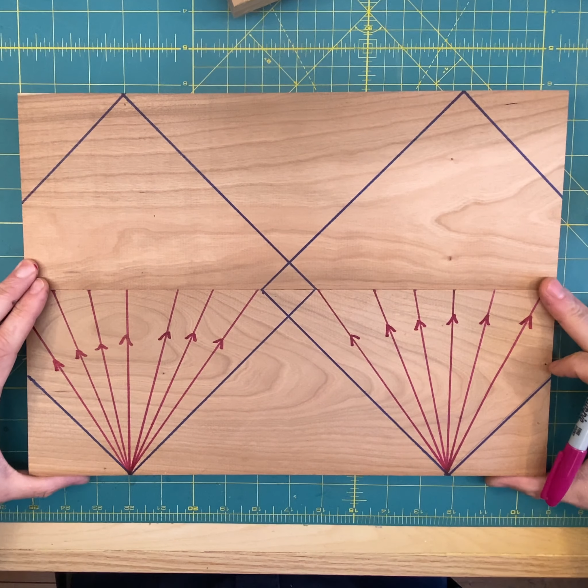
If you’re not a woodworker, you might not have heard of the “45-degree rule.” It goes like this: a clamp exerts a force that radiates out across a triangular region of the wood that forms a right angle — 45 degrees on each side of the clamp’s point of contact. So, to ensure that force is applied as evenly as possible across the entire glue joint, clamps should be spaced so that these force triangles overlap. It’s a handy rule, especially for the woodworker looking to justify the purchase of more clamps; you can never have too many clamps. But is it valid?

Myth busted?

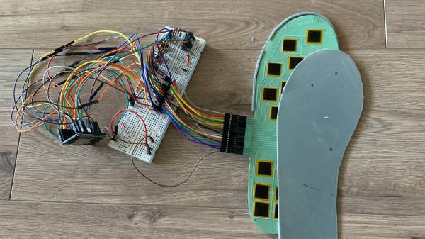
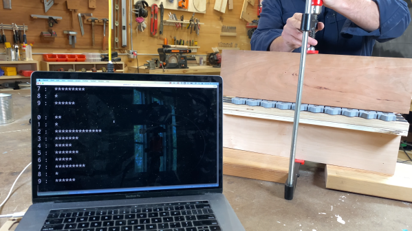
The short answer that [ari kardasis] comes up with in the video below is… sort of. With the help of a wonderfully complex array of strain gauges and a Raspberry Pi, he found that the story isn’t so simple. Each strain gauge lives in a 3D printed bracket that spaces the sensors evenly along the wood under test, with a lot of work going into making the test setup as stiff as possible with steel reinforcement. There were some problems with a few strain gauges, but once he sorted that out, the test setup went into action.

[ari] tested clamping force transmission through pieces of wood of various widths, using both hardwoods and softwoods. In general, he found that the force pattern is much broader than the 45-degree rule suggests — he got over 60 degrees in some cases. Softwoods seemed to have a somewhat more acute pattern than hardwoods, but still greater than the rulebook says. At the end of the day, it seems like clamp spacing of two board widths will suffice for hardwoods, while 1.5 or so will do for softwoods. Either way, that means fewer clamps are needed.

A lot of woodworking is seat-of-the-pants stuff, so it’s nice to see a more rigorous analysis like this. It reminds us a lot of some of the experiments [Matthia Wandel] has done, like load testing various types of woods and glues.

Continue reading “Exploring Woodworking Mysteries With Strain Gauges And Raspberry Pi”

Weigh Your Car With Paper

Sometimes a problem is more important than its solution. Humans love to solve mysteries and answer questions, but the most rewarding issues are the ones we find ourselves. Take [Surjan Singh], who wanted to see if he could calculate the weight of his Saab 96. Funny enough, he doesn’t have an automobile scale in his garage, so he had to concoct a workaround method. His solution is to multiply the pressure in his tires with their contact patch. Read on before you decide this is an imperfect idea.

He measures his tires with a quality gauge for the highest accuracy and pressurizes them equally. Our favorite part is how he measures the contact patch by sliding a couple of paper pieces from the sides until they stop and then measures the distance between them. He quickly realizes that the treads didn’t contact the floor evenly, so he measures them to get a better idea of the true contact area. Once he is satisfied, he performs his algebra and records the results, then drives to some public scales and has to pay for a weigh. His calculations are close, but he admits this could be an imprecise method due to an n-of-one, and that he didn’t account for the stiffness of the tire walls.

This was a fun thought experiment with real-world verification. If you’re one of those people who treats brainstorming like an Olympic sport, then you may enjoy the gedankenexperiment that is fractals.

Listen To Your Feet, They Have A Lot To Tell You

[Umar Qattan] is in tune with his sole and is trying hard to listen to what it has to say.

At a low level, [Umar] is building an insole with an array of force sensors in it. These sensors are affixed to a flexible PCB which is placed in a user’s shoe. A circuit containing a ESP32, IMU, and haptic feedback unit measure the sensors and send data back to a phone or a laptop.

What’s most interesting are the possibilities opened by the data he hopes to collect. The first application he proposes is AR/VR input. The feedback from the user’s feet plus the haptics could provide all sorts of interesting interaction. Another application is dynamically measuring a user’s gait throughout the day and exercise. People could save themselves a lot of knee pain with something like this.

[Umar] also proposes that an insert like this could record a user’s weight throughout the day. Using the data on the weight fluctuation, it should be possible to calculate someone’s metabolism and hydration from this data.

Instrument Packed Pedal Keeps Track Of Cyclist’s Power

Exactly how much work is required to pedal a bike? There are plenty of ways to measure the power generated by a cyclist, but a lot of them such as heavily instrumented bottom brackets and crank arms, can be far too expensive for casual use. But for $30 in parts you can build this power-measuring bike pedal. and find out just how hard you’re stoking.

Of course it’s not just the parts but knowing what to do with them, and [rabbitcreek] has put a lot of thought and engineering into this power pedal. The main business of measuring the force applied to the crank falls to a pair of micro load cells connected in parallel. A Wemos, an HX711 load-cell amp, a small LiPo pack and charging module, a Qi wireless charger, a Hall sensor, a ruggedized power switch, and some Neopixels round out the BOM. Everything is carefully stuffed into very little space in a modified mountain bike pedal and potted in epoxy for all-weather use. The Hall sensor keeps tracks of the RPMs while the strain gauges measure the force applied to the pedal, and the numbers from a ride can be downloaded later.

We recall a similar effort using a crank studded with strain gauges. But this one is impressive because everything fits in a tidy package. And the diamond plate is a nice touch.

Hacklet 89 – Star Wars Projects

Star Wars is an inspirational force to be reckoned with. Few movie franchises have quite so many fans creating everything from elaborate cosplay outfits to fully functional robots. At the 2015 Hackaday SuperCon, former R2D2 driver Grant Imahara mentioned that LucasArts used to maintain a fleet of robots to be deployed at events. Once the execs realized hacker, maker, and hobbyist robots are now more advanced than the machines they built for the actual films, they mothballed the fleet. If you see R2 at a Star Wars event this season, it’s probably an enthusiast behind the controls. This week’s Hacklet is dedicated to the best Star Wars projects on Hackaday.io!

targetshootWe start with [Nathan Gray] and Star Wars Nerf Targets. [Nathan] needed a Star Wars themed game for an event for the kids, and he needed it fast. [Nathan] built a Nerf shooting gallery game with a Star Wars twist. The idea is to shoot the bad guys with Nerf darts. Targets have two sides, so you never can be sure if you’ll see a storm trooper or a friendly Wookie. Hits are detected by piezoelectric disks on each target. A control panel starts the game, keeps score, and plays some great sound effects. An Arduino compatible Teensy 2.0 keeps everything running smoothly. [Nathan] reports that the game was a hit with the kids, and everyone else at the party. Even Grandma had to give the Star Wars Nerf Targets game a try!


vaporatorNext up is Hackaday’s own [Brian Benchoff] with The Hackaday Prize Moisture Vaporator. The 2015 Hackaday Prize promo video called for something space related. Since Southern California has plenty of desert around, a moisture vaporator straight out of Tatooine was just what the doctor ordered. [Brian], [Matt], [Rich] and [Alek] handled most of the construction at the Hackaday Hackerspace in Pasadena. Final assembly was a team effort out in the field. The basic frame of the vaporator consisted of 1 x 3 lumber joined with pocket screws. An iron pipe served as the spine. [Brian] added plenty of greebles to give the vaporator just the right look. The result makes us long for a trip to Toshi Station to pick up some power converters.

life-signs[Davedarko] is up next with Towani Lifesign Wristdevice – Star Wars Ewoks. This was one of [Dave’s] earliest projects on Hackday.io, way down at project #616. He originally built it for the Sci-Fi contest we held in 2014. The Towani family was in the Ewoks movies, which were lesser known spinoffs of the original Star Wars films. The wristbands showing the family’s vitals were featured a few times in the movies. [Dave’s] version is more than a movie prop, it actually works. He’s using an open hardware pulse sensor along with an Arduino Mini to display status on a trio of LEDs.

bb8Finally, we have [Enrico] with Our own BB-8 droid. BB-8 made a splash when he rolled out on stage during Star Wars Celebration. Everyone wondered how the original was done. We’ve since found out that the BB-8 uses Sphero’s technology to get around. However, many of the movie scenes were done with good old-fashioned puppeteer work. [Enrico] is building his own version of BB-8 using holonomic wheels inside the sphere, with a magnetically attached head. He’s planning to 3D print the major parts of his droid. So far, [Enrico] has started testing with magnets. A few printed plastic parts from his R2D2 build have been standing in for the BB-8 shell.

If you want to see more Star Wars projects, check out our new Star Wars project list! If I missed your project due to a great disturbance in the force, don’t be a nerf herder! Just drop me a message on Hackaday.io. That’s it for this week’s Hacklet. As always, see you next week. Same hack time, same hack channel, bringing you the best of Hackaday.io! May the force be with you.

Boxing Trainer

Boxing Trainer Uses DIY Force Sensors

A team of Cornell students have designed and built their own electronic boxing trainer system. The product of their work is a game similar to Whack-A-Mole. There are five square pads organized roughly into the shape of a human torso and head. Each pad will light up based on a pre-programmed pattern. When the pad lights up, it’s the player’s job to punch it! The game keeps track of the player’s accuracy as well as their reaction time.

The team was trying to keep their budget under $100, which meant that off the shelf components would be too costly. To remedy this, they designed their own force sensors. The sensors are basically a sandwich of a few different materials. In the center is a 10″ by 10″ square of ESD foam. Pressed against it is a 1/2″ thick sheet of insulating foam rubber. This foam rubber sheet has 1/4″ slits cut into it, resulting in something that looks like jail bars. Sandwiching these two pieces of foam is fine aluminum window screen. Copper wire is fixed the screen using conductive glue. Finally, the whole thing is sandwiched between flattened pieces of corrugated cardboard to protect the screen.

The sensors are mounted flat against a wall. When a user punches a sensor, it compresses. This compression causes the resistance between the two pieces of aluminum screen to change. The resistance can be measured to detect a hit. The students found that if the sensor is hit harder, more surface area becomes compressed. This results in a greater change in resistance and can then be measured as a more powerful hit. Unfortunately it would need to be calibrated depending on what is hitting the sensor, since the size of the hitter can throw off calibration.

Each sensor pad is surrounded by a strip of LEDs. The LEDs light up to indicate which pad the user is supposed to hit. Everything is controlled by an ATMEGA 1284p microcontroller. This is the latest in a string of student projects to come out of Cornell. Make sure to watch the demonstration video below. Continue reading “Boxing Trainer Uses DIY Force Sensors”