Building A Pocket Sized Arduino Oscilloscope

There’s little question that an oscilloscope is pretty much a must-have piece of equipment for the electronics hacker. It’s a critical piece of gear for reverse engineering devices and protocols, and luckily for us they’re as cheap as they’ve ever been. Even a fairly feature rich four channel scope such as the Rigol DS1054Z only costs about as much as a mid-range smartphone. But if that’s still a little too rich for your taste, and you’re willing to skimp on the features a bit, you can get a functional digital oscilloscope for little more than pocket change.

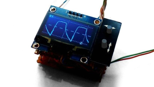
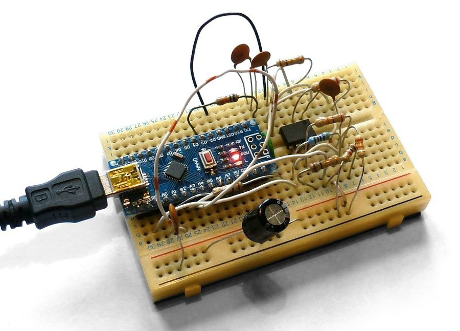
While there are a number of very cheap pocket digital storage oscilloscopes (DSOs) on the market, [Peter Balch] decided he’d rather spin up his own version using off-the-shelf components. Not only was it an excuse to deep dive on some interesting engineering challenges, but it ended up bringing the price even lower than turn-key models. Consisting of little more than an Arduino Nano and a OLED display, the cost comes out to less than $10 USD for a decent DSO that’s about the size of a matchbox.

But not a great one. [Peter] is very upfront about the limitations of this DIY pocket scope: it can’t hit very high sample rates, and the display isn’t really big enough to convey anything more than the basics. But if you’re doing some quick and dirty diagnostics in the field, that might be all you need. Especially since there’s a good chance you can build the thing out of parts from the junk bin.

Even if you’re not looking to build your own version of the Arduino-powered scope [Peter] describes, his write-up is still full of fascinating details and theory. He explains how his software approach is to disable all interrupts, and put the microcontroller into a tight polling loop to read data from the ADC as quickly as possible. It took some experimentation to find the proper prescaler value for the Atmega’s 16MHz clock, but in the end found he could get a usable (if somewhat noisy) output with a 1uS sample rate.

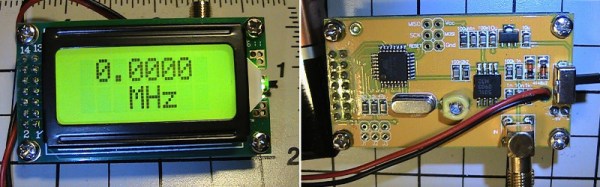
Unfortunately, the Arduino’s ADC leaves something to be desired in terms of input range. But with the addition of an LM358 dual op-amp, the Arduino scope gains some amplification so it can pick up signals down into the mV range. For completion’s sake, [Peter] included some useful features in the device’s firmware, such as a frequency counter, square wave signal source, and even a voltmeter. With the addition of a 3D printed case, this little gadget could be very handy to have in your mobile tool kit.

If you’d rather go the commercial route, Hackaday’s very own [Jenny List] has been reviewing a number of very affordable models such as the DSO Nano 3 and the JYE Tech DSO150 build-it-yourself kit.

[Thanks to BaldPower for the tip.]

Characterizing A Cheap 500MHz Counter Module

An exciting development over the last few years has been the arrival of extremely cheap instrumentation modules easily bought online and usually shipped from China. Some of them have extremely impressive paper specifications for their price, and it was one of these that caught the eye of [Carol Milazzo, KP4MD]. A frequency counter for under $14 on your favourite online retailer, and with a claimed range of 500 MHz. That could be a useful instrument in its own right, and with a range that significantly exceeds the capabilities of much more expensive bench test equipment from not so long ago.

Just how good is it though, does it live up to the promise? [Carol] presents the measurements she took from the device, so you can see for yourselves. She took look at sensitivity, VSWR, and input impedance over a wide range, after first checking its calibration against a GPS-disciplined standard and making a fine adjustment with its on-board trimmer.

In sensitivity terms it’s a bit deaf, requiring 0.11 Vrms for a lock at 10 MHz. Meanwhile its input impedance decreases from 600 ohms at the bottom of its range to 80 ohms at 200 MHz, with a corresponding shift in VSWR. So it’s never going to match a high-end bench instrument from which you’d expect much more sensitivity and a more stable impedance, but for the price we’re sure that’s something you can all work around. Meanwhile it’s worth noting from the pictures she’s posted that the board has unpopulated space for an SPI interface header, which leaves the potential for it to be used as a logging instrument.

We think it’s worth having as much information as possible about components like this one, both in terms of knowing about new entrants to the market and in knowing their true performance. So if you were curious about those cheap frequency counter modules, now thanks to [Carol] you have some idea of what they can do.

While it’s convenient to buy a counter module like this one, of course there is nothing to stop you building your own. We’ve featured many over the years, this 100MHz one using a 74-series prescaler or this ATtiny offering for example, or how about this very accomplished one with an Android UI?

Very Simple PC Frequency Counter Works Up To 100MHz

We all use 74 logic in our projects as general purpose logic interfacing glue. These chips have become as ubiquitous as a general-purpose op-amp, or even as passive components. In most cases we’re not demanding much of them, and power requirements aside an original 74 chip from the dawn of the series could probably do the same job that we’re putting a more modern variant to work on.

It is easy therefore to forget that 74 logic is a field that has seen continuous improvement and innovation reflecting the developments elsewhere in electronics, and the most modern 74 versions hide some impressively high specifications.

A good example comes via a project from [Scott, AJ4VD], a very simple frequency counter that uses a single 74 series chip at its business end, and counts to over 100MHz. The chip in question is a 74LV8154 dual 16-bit counter which he is using as a prescaler to deliver a rate more acceptable to an ATMega328 microcontroller that does the counting. As he points out, the accuracy of a frequency counter is only as good as its gate timing, and he ensures as accurate a seconds-worth of pulses as he can with a 1PPS signal derived from an inexpensive GPS receiver. The 328 makes its counting available to a host computer via a serial port, and can be easily read through a terminal. He’s built it dead-bug style on a piece of unetched PCB, on which the simplicity of the circuit is evident.

There was a time when a project like this one would have required multiple integrated circuits including a probably quite expensive purpose-built prescaler. Cheap glue logic has now advanced to a stage at which it can be done instead at commodity prices, and we like that.

We’ve featured a few 74-series counters before, including this old-school one and this one also using a 74LV8154.

Hackaday Prize Entry: A Minimal ATtiny Voltage And Frequency Counter

Sometimes when you build something it is because you have set out with a clear idea or specification in mind, but it’s not always that way. Take [kodera2t]’s project, he set out to master the ATtiny series of microcontrollers and started with simple LED flashers, but arrived eventually at something rather useful. An ATtiny10 DVM and DFM all-in-one with an i2c LCD display and a minimum of other components.

The DFM uses the ATtiny’s internal 16 bit timer, which has the convenient property of being able to be driven by an external clock. The frequency to be measured drives the timer, and the time it returns is compared to the system clock. It’s not the finest of frequency counters, depending as it does on the ATtiny’s clock rather than a calibrated crystal reference, but it does the job.

The results are shown in the video below, and all the code has been posted in his GitHub repository. We can see that there is the basis of a handy little instrument in this circuit, though with the price of cheap multimeters being so low even a circuit this minimal would struggle to compete on cost.

Continue reading “Hackaday Prize Entry: A Minimal ATtiny Voltage And Frequency Counter”

Nanocounter: Frequency Counter With An Android UI

Have you ever started a project, run into an issue, started a new project to solve the issue, and completely forgot about the original project? [Andy] went down a rabbit hole of needing a tool to calibrate an MCU oscillator, but not having an accurate way to measure frequency. Most people would just buy a frequency counter and be done with it, but [Andy] decided to build his own.

The Nanocounter is an accurate, open source frequency counter that uses an Android phone as its display. It’s based on a high accuracy temperature compensated crystal oscillator (TCXO) fed into a phase locked loop (PLL) to create a high frequency, accurate reference clock.

This reference clock, along with the signal to be measured, are sent into a Xilinx FPGA which uses a method called equal precision measurement to determine the frequency. A STM32F072 microcontroller uses a SPI interface to get this data out of the FPGA, and controls the whole system. Finally, a cheap HC-06 Bluetooth module facilitates communication with an Android device.

The project achieves the goal of frequency counting, though [Andy] doesn’t remember what project sparked the idea to build it. (Classic yak shaving!) But the result is a great read of a detailed writeup, and you can watch a video of the Nanocounter in action after the break. That’s a win in our book.

Continue reading “Nanocounter: Frequency Counter With An Android UI”

XOXO For The OCXO

HPocxo

[Kerry Wong] recently got himself a frequency counter. Not just any counter, a classic Hewlett-Packard 5350B Microwave Counter. This baby will go 10Hz all the way up to 20GHz with only one input shift. A true fan of Hackaday Prize judge [Dave Jones], [Kerry] didn’t turn it on, he took it apart. In the process, he gave us some great pictures of late 80’s vintage HP iron.

Everything seemed to be in relatively good working order, with the exception of the oven indicator, which never turned off. The 5350B had three time bases available: a Thermally Compensated Crystal Oscillator (TCXO),  an Oven Controlled Crystal Oscillator (OCXO), and a high stability OCXO. [Kerry’s] 5350B had option 001, the OCXO. Considering it was only a $750 USD upgrade to the 5350B’s $5500 USD base price, it’s not surprising that many 5350B’s in the wild have this option.

[Kerry] checked the wattage of his 5350B, and determined that it pulled about 27 watts at power up and stayed there. If the OCXO was working, wattage would have dropped after about 10 minutes when the oven came up to temperature. Time to tear open an oven!

Armed with a copy of the 5350B service manual from HP’s website, [Kerry] opened up his OCXO. The Darlington transistors used as heaters were fine. The control circuit was fine. The problem turned out to be a simple thermal fuse. The service manual recommended jumping out the fuse for testing. With the fuse jumped, the oven came to life. One more piece of classic (and still very useful) test equipment brought back to full operation.

[via Dangerous Prototypes]

DIY High Stability Timebase Hack For ~$25. Why? Frequency Stability Matters!

DIY High Stability Timebase OCXO

If you have an old “Racal-Dana 199x” frequency counter or similar 10 MHz internally referenced gear with a poor tolerance “standard quartz crystal oscillator” or bit better “temperature compensated crystal oscillator” (TCXO) you could upgrade to a high stability timebase “oven controlled crystal oscillator” (OCXO) for under $25. [Gerry Sweeney] shares his design and fabrication instructions for a DIY OCXO circuit he made for his Racal-Dana frequency counter. We have seen [Gerry] perform a similar upgrade to his HP 53151A, however, this circuit is more generic and can be lashed up on a small section of solderable perf board.

Oven controlled oscillators keep the crystal at a stable temperature which in turn improves frequency stability. Depending on where you’re starting, adding an OCXO could improve your frequency tolerance by 1 to 3 orders of magnitude. Sure, this isn’t as good as a rubidium frequency standard build like we have seen in the past, but as [Gerry] states it is nice to have a transportable standalone frequency counter that doesn’t have to be plugged into his rubidium frequency standard.

[Gerry’s] instructions, schematics and datasheets can be used to upgrade any lab gear which depends on a simple 10 MHz reference (crystal or TXCO). He purchased the OCXO off eBay for about $20 — it might be very old, yet we are assured they get more stable with age. Many OCXO’s require 5 V, 12 V or 24 V so your gear needs to accommodate the correct voltage and current load. To calibrate the OCXO you need a temperature stable variable voltage reference that can be adjusted from 1 to 4 volts. The MAX6198A he had on hand fit the bill at 5 ppm/°C temperature coefficient. Also of importance was to keep the voltage reference and trim pot just above the oven for added temperature stability as well as removing any heat transfer through the mounting screw.

You can watch the video and get more details after the break.

Continue reading “DIY High Stability Timebase Hack For ~$25. Why? Frequency Stability Matters!”