Pool Playing Robot Destined For Trouble In River City

You’d think pool should be an easy game for a robot to play, right? It’s all math — geometry to figure out the angles and basic physics to deal with how much force is needed to move the balls. On top of that, it’s constrained to just two dimensions, so it should be a breeze.

Any pool player will tell you there’s much, much more to the game in real life, but still, a robot to play pool against would be a neat trick. As a move toward that goal, [BVarv] wisely decided on a miniature mockup of a pool-playing robot, and in the process reinvented the pool table itself. Realizing that a tracked or wheeled robot would have a tough time maneuvering around the base of a traditional pool table, his model pool table is a legless design that looks like something from IKEA. But the pedestal support allows the robot to be attached to the table and swing around in a full circle, and this allowed him to work through the kinematics as shown in the charming stop-action video below.

[BVarv] has gotten as far as motion control on the swing axis, as well as on the arms that will eventually hold the cue. He plans overhead image analysis for identifying shots, and of course there’s the whole making it full-size thing to do. We’d love to play a game or two against a bot, so we hope he gets there. In the meantime, how about a little robo-air hockey?

Continue reading “Pool Playing Robot Destined For Trouble In River City”

Laser Surgery: Expanding The Bed Of A Cheap Chinese Laser Cutter

Don’t you just hate it when you spend less than $400 on a 40-watt laser cutter and it turns out to have a work area the size of a sheet of copy paper? [Kostas Filosofou] sure did, but rather than stick with that limited work envelope, he modified his cheap K40 laser cutter so it has almost five times the original space.

The K40 doesn’t make any pretenses — it’s a cheap laser cutter and engraver from China. But with new units going for $344 on eBay now, it’s almost a no-brainer. Even with its limitations, you’re still getting a 40-watt CO2 laser and decent motion control hardware to play with. [Kostas] began the embiggening by removing the high-voltage power supply from its original space-hogging home to the right of the work area. With that living in a new outboard enclosure, a new X-Y gantry of extruded aluminum rails and 3D-printed parts was built, and a better exhaust fan was installed. Custom mirror assemblies were turned, better fans were added to the radiator, and oh yeah — he added a Z-axis to the bed too.

We’re sure [Kostas] ran the tab up a little on this build, but when you’re spending so little to start with, it’s easy to get carried away. Speaking of which, if you feel the need for an even bigger cutter, an enormous 100-watt unit might be more your style.

Continue reading “Laser Surgery: Expanding The Bed Of A Cheap Chinese Laser Cutter”

Dartboard Watches Your Throw; Catches Perfect Bullseyes

Some people really put a lot of effort into rigging the system. Why spend years practicing a skill and honing your technique to hit a perfect bullseye in darts when you can spend the time building an incredibly complicated auto-bullseye dartboard that’ll do it for you?

In fairness, what [Mark Rober] started three years ago seemed like a pretty simple task. He wanted to build a rig to move the dartboard’s bullseye to meet the predicted impact of any throw. Seems simple, but it turns out to be rather difficult, especially when you choose to roll your own motion capture system.

That system, built around the Nvidia Jetson TX1, never quite gelled, a fact which unfortunately burned through the first two years of the project. [Mark] eventually turned to the not inexpensive Vicon Vantage motion capture system with six IR cameras. A retroreflector on the non-regulation dart is tracked by the system and the resulting XY data is fed into MATLAB to calculate the parabolic path of the dart. An XY-gantry using six steppers quickly shifts the board so the bullseye is in the right place to catch the incoming dart.

It’s a huge amount of work and a lot of money to spend, but the group down at the local bar seemed to enjoy it. We wonder if it can be simplified, though. Perhaps tracking just the thrower’s motions with an IMU-based motion capture system and extrapolating the impact point would work.

Continue reading “Dartboard Watches Your Throw; Catches Perfect Bullseyes”

Impressive Junkyard CNC Made From Fancy Garbage

We’ll just come out and say it, [reboots] has friends with nice garbage. Sure, some of us have friends who are desperately trying to, “gift,” us a CRT monitor, hope dropping like a rock into their stomach when they realize they can’t escape the recycling fee.  [reboots] has friends who buy other people’s poorly thought out CNC projects and then gift him with the parts.

After dismantling the contraption he found himself with nice US and Japanese made linear motion components. However, he needed a CNC controller to drive it all. So he helped another friend clean out their garage and came away with a FlashCut CNC controller.

Now that he had a controller and the motion components whirring nicely, he really needed a frame to put it all in. We like to imagine that he was at a friend’s  barbeque having a beer. In one corner of the yard was an entire Boeing 747.  A mouldering scanning electron microscope with a tattered and faded blue tarp barely covering its delicate instrumentation sat in another corner. Countless tech treasures were scattered about in various states. It was then that he spotted a rusting gamma ray spectrometer in the corner that just happened to have the perfect, rigid, gantry frame for his CNC machine.

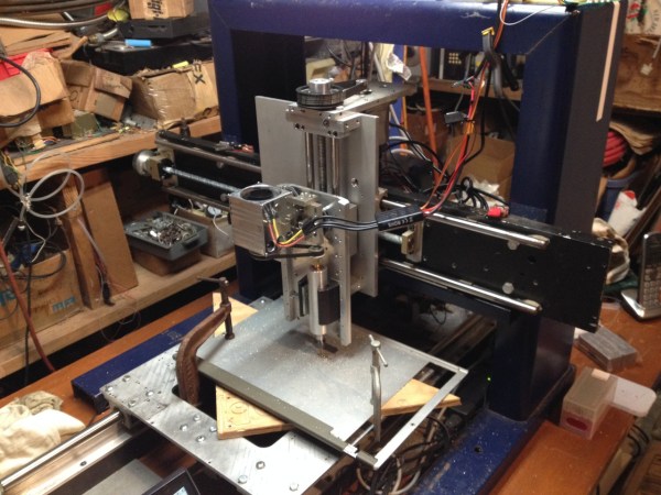
Of course, his friend obliged and gladly gave up the spectrometer. Now it was time to put all together. The gantry was set on a scavenged institutional door. The linear motion frames were bolted in place. Quite a few components had to be made, naturally, of scrap materials.

spindletest2
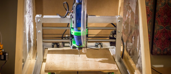
Most people will start by using a handheld router for the spindle. The benefits are obvious: they’re inexpensive, easy to procure, and generally come with mounts. But, there are some definite downsides, one of the most glaring of which is the lack of true speed control.

Even routers that allow you to adjust the speed (a fairly common feature on new models) generally don’t actually regulate that speed. So, you end up with a handful of speed settings which aren’t even predictable under load. Furthermore, they usually rely on high RPMs to do their work. For those reasons, handheld woodworking routers aren’t the best choice for a mill that you intend to cut metal with.

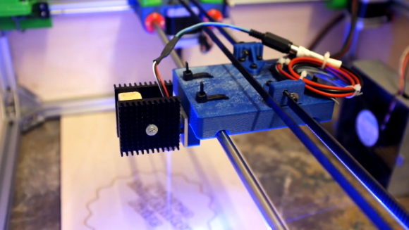
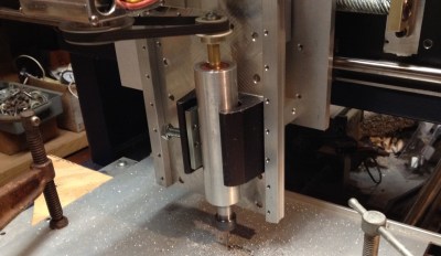
[reboots] noticed this problem while building this machine and came up with an inexpensive way to build a speed-controlled spindle. His design uses a brushless DC motor, controlled through a hobby ESC (electronic speed control), which uses a belt to drive the spindle. The spindle itself is mounted using skateboard bearings, and ends in an E11 collet (suitable for light machining in aluminum).

With the ESC providing control of the brushless motor, he’s able to directly control the spindle speed via software. This means that spindle speeds can be changed with G-code, allowing for optimized feeds and speeds for different operations. The belt-drive increases torque while separating the motor from the spindle, which should keep things cool, and reduce rotating mass on the spindle itself. Now all [reboots] needs to do is add a DIY tool changer!

A CNC You Could Pop-Rivet Together

You have to be careful with CNC; it’s a slippery slope. You start off one day just trying out a 3D printer, and it’s not six months before you’re elbow deep in a discarded Xerox looking for stepper motors and precision rods. This is evident from [Dan] and his brother’s angle aluminum CNC build.

Five or six years ago they teamed up to build one of those MDF CNC routers. It was okay, but really only cut foam. So they moved on to a Rostock 3D printer. This worked much better, and for a few years it sated them. However, recently, they just weren’t getting what they needed from it. The 3D printer had taught them a lot of new things, 3D modeling, the ins of running a CNC, and a whole slew of making skills. They decided to tackle the CNC again.

The new design is simple and cheap. The frame is angle aluminum held together with screws. The motion components are all 3D printed. The spindle is just an import rotary tool. It’s a simple design, and it should serve them well for light, low precision cuts. We suspect that it’s not the last machine the pair will build. You can see it in action in the video after the break.

Continue reading “A CNC You Could Pop-Rivet Together”

Extruded Rail And 3D Printed Connectors Form A Proper Laser Engraver

3d-printed-laser-engraver

Fast and accurate is a good description of this laser engraver built by [Ragnar] and [Gunnar]. The’re planning to show it off at the Trondheim Maker Faire after the new year but they took it out in the wild for the PSTEREO Mini Maker Faire (also in Trondheim) this past August. The video below gives an overview of the build process and the engraver at work. But we also enjoyed reading the post about a few missteps in the early prototyping process. We call this one a proper laser engraver because it was purpose built from the ground-up. We still like seeing the engravers hacked from optical drives, but this really is a horse of a different color in comparison.

From the start they’re using familiar parts when it comes to CNC builds. The outer frame is made of extruded aluminum rail, with precision rod for the gantry to slide upon. Movement is facilitated with stepper motors and toothed belts, with all of the connecting and mounting parts fabricated on a 3D printer. The mistake made with an early (and unfortunately mostly assembled) prototype was that the Y axis was only driven on one side when it really needed to be driven on both. But filament is relatively cheap so a few tweaks to the design were able to fix this and get the production back on track.

Continue reading “Extruded Rail And 3D Printed Connectors Form A Proper Laser Engraver”

Magnetic CNC Marble Maze

magnetic-cnc-marble-maze

[Martin Raynsford] figured out a way to sneak some learning into a fun package. He did such a good job the test subjects didn’t even know they were teaching themselves just a tiny bit of CNC programming.

The apparatus above is a marble maze, but instead of building walls [Martin] simply etched a pattern on the playing field. The marble is a ball bearing which moves through the maze using a magnetic CNC gantry hidden underneath. Where does one get ball bearings of this size? If you’re [Martin] you scavenge them from your laser-cut Donkey Kong game.

He showed off the rig at the Maker Faire.  It takes simple commands as cardinal directions and units of movement. The ‘player’ (remember, they’re secretly learning something, not just playing a game) inputs a series of movements such as “N10,E10” which are then pushed through a serial connection to the Arduino. It follows these commands, moving the hidden magnet which drags the ball bearing along with it. It’s simple, but watch the clip after the break and we think you’ll agree the sound of the stepper motors and the movement of the ball will be like crack for young minds.

Continue reading “Magnetic CNC Marble Maze”