Two-wire Serial Backpack For GLCD Screens

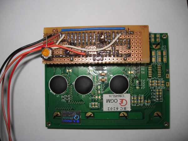
[Debraj] wrote in about his 2-wire serial backpack he developed for a Graphic LCD screen. It’s build on a hunk of protoboard and uses a pair of 595 shift registers to translate incoming serial data to the parallel interface which is used by the LCD screen. It takes more time to push commands this way, but the interface is still quite snappy as you can see in the clip after the jump.

The real trick here is how the hardware has been configured to get away without a third wire for latching the shift registers (if you need a primer on 595 chips check out this feature). The idea of using a latch is that all of the data can be shifted in over the serial pin before it appears on the output pins. Otherwise, the GLCD would see each bit as it shifts into the register, wreaking havoc on its communication protocol. [Debraj] gets around this by using a diode AND gate trick he learned from this other serial LCD project.

One good thing about this method is the 595 chips have a wide range of control voltage that will allow you to drive this with 3.3V or 5V microcontrollers. But you do need to implement the communication protocol and push those commands via serial. For nearly the same cost in chips something like an ATtiny2313 could be substituted to make an even simpler addressing scheme — or even switch to 1-wire protocol. But you’d then lose the wide input voltage tolerance.

Continue reading “Two-wire Serial Backpack For GLCD Screens”

Driving A T6963C Based Graphic LCD

[Tom Fleet] spent the dreary weekend inside learning how to drive this T6963C based graphic LCD controller. Although this is his first time venturing away from HD44780 character displays, the availability of an Arduino library helped him go from being a newbie to coding his own animated graphics.

The hardware setup is straight-forward. The screen has a 20-pin connector and operates at 5V. We don’t see it on his protoboard, but usually these displays also need a potentiometer which serves as a voltage divider for the screen contrast. The data and control pins eat up most of the available I/O on the ATmega328 chip he used, but the I2C and SPI pins are still open and he plans a future project to make this a wireless display for his PC using one of those protocols.

As for fonts and animation, [Tom] links to several tools which will come in handy. There’s a font program that will convert Windows system fonts into a C file for use on the Arduino. The animations start with a 1:1 ratio animated graphic drawn with his favorite image editing software. He then converts those to monochrome bmp files and used bmp2c to convert each frame to a C array. After the break there’s a seven second example that would work well as a boot screen for his project.

Continue reading “Driving A T6963C Based Graphic LCD”

Slot Car Lap Timer/counter

For his first project using the TI Launchpad [VOJT4] built a lap timer and counter for slot cars. For us it’s always hardest to come up with the idea of what to build and we think he found a great one here.

Each time a car passes the finish line of the track it trips a reed switch that was hot glued to the underside of the track segment. Both reed switches have a capacitor to smooth out the inputs (is this acting as a hardware debounce?). The time and lap number are then pushed to a graphic LCD by the MSP430G2553.

You must be logged into the forum where [VOJT4] posted the project in order to see the images. Because of this, we’ve embedded them (including the schematic) after the break along with a demo video. But do take a look at his project thread to hear his thoughts and peruse the code he wrote.

Continue reading “Slot Car Lap Timer/counter”

Learn The Geometry To Draw An Analog Clock On A Graphic LCD Screen

Does the image of the clock above make you shutter with fear because of the math you’d need to use to recreate your own version of the project? We certainly understand that High School geometry is becoming a very distant memory, but it’s really not as hard as you think. [Janw] built this analog clock using a graphic LCD and he’s done a great job of explaining the concepts behind it.

The hardware he’s using is pretty standard for an electronic hobby clock; an ATmega16, graphic LCD, DS1307 real-time clock, and supporting hardware like a potentiometer, resistors, and buttons. The code is written in Bascom, but like we said, [Janw] explains the concepts behind drawing the hands on the clock so you can recreate this with any microcontroller or software language you prefer. We  recommend grabbing a calculator and some blank paper. It took us a few tries to brush the cobwebs out and really grasp what he’s doing with each equation.

Overclocked ATmega32 Gaming

With more pixels and more objects to track you’re going to need to get that AVR running pretty fast to get the job done. But [Vladutz2000] figured why stop at 16 MHz when you can overclock an ATmega32 to 27 MHz for a faster gaming experience?

This build may not be as colorful as Super Pixel Bros, but choosing a KS0108 graphic LCD certainly brings a lot more definition to the images. You can see in the video after the break that the AVR does an excellent job of generating and animating multiple objects. It doesn’t take much to put this together yourself but if you want the board layout done for you, you’re out of luck. The hardware for the project is installed on a PCB that was hand-drawn with an etch resist marker. Continue reading “Overclocked ATmega32 Gaming”

Bench Supply With Current Limiting

This is a bench power supply with adjustable voltage and current limiting. [Sylvain’s] creation can regulate 0-25 volts while sourcing 0-5 amps. Current limiting is a nice feature as it will allow you to test your prototypes to ensure the power regulator you choose will not be over or underpowered.

This supply is really a two-in-one. The case has two separate circuits so that you can have different power rails going at the same time. There is a microcontroller involved, but the ATmega32 doesn’t do anything more than measure the voltage and amperage and drive the graphic LCD screen. Two potentiometers are responsible for setting the voltage and limiting the current.

[Thanks Sargonout]