FET Based Motor Driver Is Better Than L298N

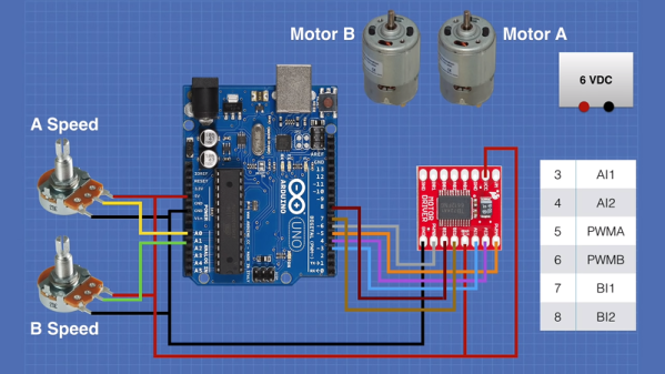
If you want to build a small robot with a motor, you are likely to reach for an L298N to interface your microcontroller to the motor, probably in an H-bridge configuration. [Dronebot] has used L298N chips like this many times. In the video below, he uses a TB6612FNG instead, taking advantage of the device’s use of MOSFETs. The TB6612 may be a little more expensive, but it’s clearly worth it.

You can get breakout boards for the tiny chips. [DroneBot] looks at several ready-to-go breakout boards. They are not drop-in compatible, though. For example, the L298N can operate motors from 4.5 to 46V while the TB6612 can go from 2.5 to 13.5V on the motor voltage. The L298N also handles more current. However, because of its relatively low efficiency, it needs a heat sink. The TB6612 boasts up to 95% efficiency and also has a low current standby mode. Of course, the TB6612 drops much less voltage which is great if you are using low voltage motor.

Continue reading “FET Based Motor Driver Is Better Than L298N”

Stepper-Controlled Chop Saw Automates A Tedious Job

We’re not going to question why [Absorber Of Light] needs to cut a bazillion little fragments of aluminum stock. We assume his reasoning is sound, so all we’re interested in is the automated chop saw he built to make the job less tedious, and potentially less finger-choppy.

There are probably many ways to go about this job, but  [Absorber] leaves few clues as to why he chose this particular setup. Whatever the reason, the build looks like fun, with a long, stepper-driven threaded rod pushing a follower down a track to a standard chop saw. The aluminum stock rides in the track and gets pushed out a set amount before being lopped off cleanly as the running saw is lowered by a linear actuator. The cycle then repeats until the stock is gone.

An Arduino controls the stock-advance stepper in the usual way, but the control method for the linear actuator is somewhat unconventional. A second stepper motor has two cams offset by 180° on the shaft. The cams actuate four microswitches which are set up in an H-bridge configuration. The stepper swivels back and forth to run the linear actuator first in one direction then the other, with a neutral position in between. It’s an interesting approach using mechanical rather than the typical optical isolation. Check it out in action in the video below.

We’ll admit to some curiosity as to the use of the coupons this rig produces, so maybe we’ll get lucky with some details from [Absorber Of Light] in the comment section. After all, we knew exactly what the brass tubes being cut by the similar “Auto Mega Cut-O-Matic”  were being used for.

Continue reading “Stepper-Controlled Chop Saw Automates A Tedious Job”

Split Flap Clock Keeps Time Thanks To Custom Frequency Converter

Why would anyone put as much effort into resurrecting a 1970s split-flap clock as [mitxela] did when he built this custom PLL frequency converter? We’re not sure, but we do like the results.

The clock is a recreation of the prop from the classic 1993 film, Groundhog Day, rigged to play nothing but “I Got You Babe” using the usual sound boards and such. But the interesting part was getting the clock mechanism keeping decent time. Sourced from the US, the clock wanted 120 VAC at 60 Hz rather than the 240 VAC, 50 Hz UK standard. The voltage difference could be easily handled, but the frequency mismatch left the clock running unacceptably slow.

That’s when [mitxela] went all in and designed a custom circuit to convert the 50 Hz mains to 60 Hz. What’s more, he decided to lock his synthesized waveform to the supply current, to take advantage of the long-term frequency control power producers are known for. The write-up goes into great detail about the design of the phase-locked loop (PLL), which uses an ATtiny85 to monitor the rising edge of the mains supply and generate the PWM signal that results in six cycles out for every five cycles in. The result is that the clock keeps decent time now, and he learned a little something too.

If the name [mitxela] seems familiar, it’s probably because we’ve featured many of his awesome builds before. From ludicrous-scale soldering to a thermal printer Polaroid to a Morse-to-USB keyboard, he’s always got something cool going on.

Electromechanical YouTube Sub Counter Trades Clicks For Clacks

Acquiring a new YouTube subscriber is a blessed event that deserves far more fanfare than a phone notification. But maybe blinkenlights don’t really do it for you anymore, or you simply prefer to be soothed sonically rather than visually. Well, what could be more satisfying than the crisp clack of an electromechanical 7-segment display? Six of them, of course. These things look great, they sound great, and once they’re set, they don’t need power to stay that way.

These displays switch between black and white by reversing current flow through their electromagnets, so [Zack] turned to the H-bridge in order to use them with DC. One H-bridge for each segment of six displays adds up fast, though. To get around this, [Zack] tied one pole of each electromagnet together for a common signal input, and used the other pole to control each segment individually. Then, he was able to tie all the A segments together, all the B segments, and so on, and only needs 13 H-bridges to do it all.

There was just one thing [Zack] didn’t count on. Once he got the board soldered up and running, the displays started acting funny. The low impedance of the coils was causing them to influence each other over the common path, so he added diode arrays to keep them in line.

[Zack]’s using an ESP32 to get the 411 through the Google API, and four octal serial switches to drive the displays. Even more satisfying than all those clacks is the displays’ operational economy baked into [Zack]’s code—as they count up, any segments common to the first digit and the next digit remain on. Increment your way past the break to check out the build video.

Not focused on numbers, but still want to celebrate each new sub? Try a dancing robot or a Tetris twist.

Continue reading “Electromechanical YouTube Sub Counter Trades Clicks For Clacks”

How To Build An Inverter, And Why Not To Bother

It’s ridiculously easy to lay hands on a cheap DC-to-AC inverter these days. They’re in just about every discount or variety store and let you magically plug in mains powered devices where no outlets exist. Need 120- or 240-VAC in your car? No problem – a little unit that plugs into the lighter socket is available for a few bucks.

So are these commodity items worth building yourself? Probably not as [GreatScott!] explains, but learning how they work and what their limitations are will probably help your designs. The cheapest and most common inverters have modified square wave outputs, which yield a waveform that’s good enough for most electronics and avoids the extra expense of producing a pure sinusoidal output. He explains that the waveform is just a square wave with a slight delay at the zero-crossing points to achieve the stepped pattern, and shows a simple H-bridge circuit to produce it. He chose to drive the output section with an Arduino, to easily produce the zero-crossing delay. He uses this low-voltage inverter to demonstrate how much more complicated the design needs to get to overcome the spikes caused by inductive loads and the lack of feedback from the output.

Bottom line: it’s nice to know how inverters work, but some things are better bought than built. That won’t stop people from building them, of course, and knowing what you’re doing in this field has been worth big bucks in the past.

Continue reading “How To Build An Inverter, And Why Not To Bother”

High Voltage Switching With MOSFETs

Using a MOSFET as a switch is generally pretty simple. Make the gate voltage sufficient with respect to the source and current flows through the channel. However, if you are switching higher voltages, you may need some additional circuitry to protect the device’s gate and possibly the microcontroller driving the whole thing, too. [Lewis] discusses high voltage switching in the latest in his series of videos dealing with MOSFETs. You can see the video below.

You’ll see in the video a breadboard setup driving a 50 V load and also a higher-voltage H-bridge. There are three major topics covered: Using an optoisolator, using a gate bleeder resistor, and using a zener diode to limit gate voltage.

Continue reading “High Voltage Switching With MOSFETs”

Dive Inside This Old Quartz Watch

In an age of smartwatches, an analog watch might seem a little old-fashioned. Whether it’s powered by springs or a battery, though, the machinery that spins those little hands is pretty fascinating. Trouble is, taking one apart usually doesn’t reveal too much about their tiny workings, unless you get up close and personal like with this microscopic tour of an analog watch.

This one might seem like a bit of a departure from [electronupdate]’s usual explorations of the dies within various chips, but fear not, for this watch has an electronic movement. The gross anatomy is simple: a battery, a coil for a tiny stepper motor, and the gears needed to rotate the hands. But the driver chip is where the action is. With some beautiful die shots, [electronupdate] walks us through the various areas of the chip – the oscillator, the 15-stage divider cascade that changes the 32.768 kHz signal to a 1 Hz pulse, and a remarkably tiny H-bridge for running the stepper. We found that last section particularly lovely, and always enjoy seeing the structures traced out. There are even some great tips about using GIMP for image processing. Check out the video after the break.

[electronupdate] knows his way around a die, and he’s a great silicon tour guide, whether it’s the guts of an SMT inductor or a Neopixel close-up. He’s also looking to improve his teardowns with a lapping machine, but there are a few problems with that one so far.

Continue reading “Dive Inside This Old Quartz Watch”