Harmonic Drive Uses Compliant Mechanism To Slim Down

[Levi Janssen] has a secret: he doesn’t like harmonic drives. But rather than abandon the torque-amplifying transmission completely, he decided to see about improving them using 3D-printed compliant mechanisms.

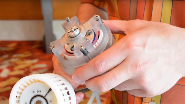
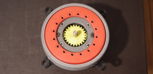
For the uninitiated, harmonic drives, also known as strain-wave gears, are a compact, high-torque gearbox that has become popular with “robotic dog” makers and other roboticists. The idea is to have a rigid, internally-toothed outer ring nested around an externally-toothed, flexible cup. A wave generator rotates within the inside cup, stretching it so that it meshes with the outer ring. The two gears differ by only a couple of teeth, meaning that very high gear ratios can be achieved, which makes them great for the joints of robot legs.

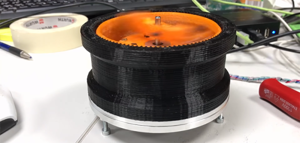
[Levi]’s problem with the harmonic drive is that due to the depth of the flexible spline cup, compactness is not among its virtues. His idea is to couple the flex spline to the output of the drive through a flat spring, one that allows flexion as the wave generator rotates but transmits torque efficiently. The entire prototype is 3D-printed, except for the wave generator bearings and stepper motor, and put to the test.

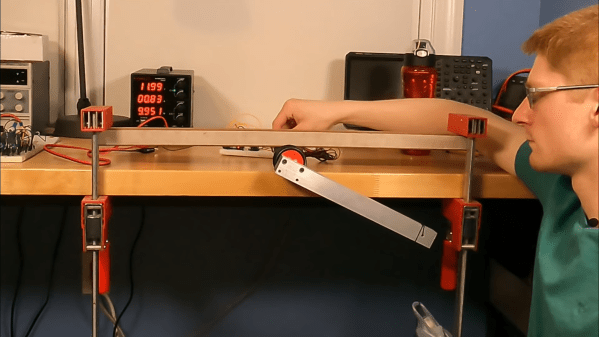
As the video below shows after the excellent introduction to harmonic drives, the concept works, but it’s not without its limitations. Even lightly loaded, the drive made some unpleasant crunching sounds as the PLA springs gave out. We could easily see that being replaced with, say, a steel spring, either machined or cut on a water-jet machine. That might solve the most obvious problem and make [Levi]’s dream of a compact harmonic drive a reality. Of course, we have seen pretty compact strain-wave gears before.

Continue reading “Harmonic Drive Uses Compliant Mechanism To Slim Down”

Harmonic Analyzer Does It With Cranks And Gears

Before graphic calculators and microcomputers, plotting functions were generally achieved by hand. However, there were mechanical graphing tools, too. With the help of a laser cutter, it’s even possible to make your own!

The build in question is nicknamed the Harmonic Analyzer. It can be used to draw functions created by adding sine waves, a la the Fourier series. While a true Fourier series is the sum of an infinite number of sine waves, this mechanical contraption settles on just 5.

This is achieved through the use of a crank driving a series of gears. The x-axis gearing pans the notepad from left to right. The function gearing has a series of gears for each of the 5 sinewaves, which work with levers to set the magnitude of the coefficients for each component of the function. These levers are then hooked up to a spring system, which adds the outputs of each sine wave together. This spring adder then controls the y-axis motion of the pen, which draws the function on paper.

It’s a great example of the capabilities of mechanical computing, even if it’s unlikely to ever run Quake. Other DIY mechanical computers we’ve seen include the Digi-Comp I and a wildly complex Differential Analyzer. Video after the break.

Continue reading “Harmonic Analyzer Does It With Cranks And Gears”

Your USB Serial Adapter Just Became A SDR

To say that the RTL-SDR project was revolutionary might be something of an understatement. Taking a cheap little USB gadget and using it as a Software Defined Radio (SDR) to explore the radio spectrum from the tens of megahertz all the way into gigahertz frequencies with the addition of nothing more than some open source tools may go down as one of the greatest hacks of the decade. But even in the era of RTL-SDR, what [Ted Yapo] has manged to pull off is still pretty incredible.

With a Python script, a length of wire attached to the TX pin, and a mastery of the electron that we mere mortals can only hope to achieve, [Ted] has demonstrated using a common USB to serial adapter as an SDR transmitter. That’s right, using the cheap little UART adapter you’ve almost certainly got sitting in your parts bin right now and his software, you can transmit in the low megahertz frequencies and even up into VHF with some trickery. The project is still very much experimental, and though this may be the first time, we’re willing to bet this isn’t the last time you’ll be hearing about it.

The basic idea is that when sending certain characters over the UART serial line, they can combine with the start and stop bits to produce a square wave burst at half the baud rate. [Ted] found that sending a string of 0x55 at 19200 baud would generate a continuous square wave at 9600 Hz, and if he turned the baud rate all the way up to 2,000,000 where these USB adapters top out, that signal was transmitted at 1 MHz, right in the middle of the AM dial.

A neat trick to be sure, but alone not terribly useful. The next step was to modulate that signal by sending different characters over UART. [Ted] explains at great length his experiments with multi-level quantization and delta-sigma schemes, and each step of the way shows the improvement of the transmitted audio signal. Ultimately he comes up with a modulation scheme that produces a impressively clean signal, all things considered.

This alone is impressive, but [Ted] isn’t done yet. He realized that this method of transmission was generating some strong frequency harmonics which extended far beyond the theoretical maximum 1 MHz frequency of his UART SDR. In his experimentation he found he was able to pick up a signal from all the way out to 151 MHz, though it was too poor to be of any practical use. Dialing back the expectations a bit, he was able to successfully control a cheap 27 MHz RC toy using the 43rd harmonic of a 631 kHz signal at a range of about 10 feet with a FT232RL adapter, which he notes produces the cleanest signals in his testing.

[Ted] is still working on making transmissions cleaner and stronger by adding filters and amplifiers, but these early accomplishments are already very promising. His work reminds us of a low frequency version of the USB to VGA adapter turned GHz SDR transmitter, and we’re very eager to see where it goes from here.

Continue reading “Your USB Serial Adapter Just Became A SDR”

Printing Strain Wave Gears

We just wrapped up the Robotics Module Challenge portion of the Hackaday Prize, and if there’s one thing robots need to do, it’s move. This usually means some sort of motor, but you’ll probably want a gear system on there as well. Gotta have that torque, you know.

For his Hackaday Prize entry, [Johannes] is building a 3D printed Strain Wave Gear. A strain wave gear has a flexible middle piece that touches an outer gear rack when pushed by an oval central rotor. The difference in the number of teeth on the flexible collar and the outer rack determine the gear ratio.

This gear is almost entirely 3D printed, and the parts don’t need to be made of flexible filament or have weird support structures. It’s printed out of PETG, which [Johannes] says is slippery enough for a harmonic drive, and the NEMA 17 stepper is completely contained within the housing of the gear itself.

Printing a gear system is all well and good, but what do you do with it? As an experiment, [Johannes] slapped two of these motors together along with a strange, bone-like adapter to create a pan/tilt mount for a camera. Yes, if you don’t look at the weird pink and blue bone for a second, it’s just a DSLR on a tripod with a gimbal. The angular resolution of this setup is 0.03 degrees, so it should be possible to use this setup for astrophotography. Impressive, even if that particular implementation does look a little weird.

Continue reading “Printing Strain Wave Gears”

Pulleys Within Pulleys Form A Unique Transmission For Robots

After a couple of millennia of fiddling with gears, you’d think there wouldn’t be much new ground to explore in the field of power transmission. And then you see something like an infinitely variable transmission built from nested pulleys, and you realize there’s always room for improvement.

The electric motors generally used in robotics can be extremely efficient, often topping 90% efficiency at high speed and low torque. Slap on a traditional fixed-ratio gearbox, or change the input speed, and efficiency is lost. An infinitely variable transmission, like [Alexander Kernbaum]’s cleverly named Inception Drive, allows the motor to stay at peak efficiency while smoothly changing the gear ratio through a wide range.

The mechanism takes a bit of thought to fully grok, but it basically uses a pair of split pulleys with variable spacing. The input shaft rotates the inner pulley eccentrically, which effectively “walks” a wide V-belt around a fixed outer pulley. This drives the inner pulley at a ratio depending on the spacing of the pulley halves; the transmission can shift smoothly from forward to reverse and even keep itself in neutral. The video below will help you get your head around it.

We’ve seen a couple of innovative transmissions around here lately; some, like this strain-wave gear and this planetary gearbox, are amenable to 3D printing. Looks like the Inception Drive could be printed too. Hackers, start your printers and see what this drive can do.

Continue reading “Pulleys Within Pulleys Form A Unique Transmission For Robots”

Unique Planetary Gearbox Can Be Custom Printed For Steppers

Stepper motors are a staple in all sorts of projects, but it’s often the case that a gearbox is needed, especially for applications like the linear drives in CNC machines and 3D printers. In those mechanisms, a high-torque, low backlash gearbox might be just the thing, and a 3D printable split planetary harmonic drive for the popular NEMA 17 motors would be even better.

Right up front, we’ll say that we’re skeptical that any plastic gearbox can stay as backlash free as [SirekSBurom] claims his creation is. But we can see the benefits of the design, and it has some nice features. First off, of course, is that it’s entirely 3D printed, except for a few screws. That it mates perfectly with a NEMA 17 motor is a really nice feature, too, and with the design up on Thingiverse it shouldn’t be too tough to scale it up and down accordingly. The videos below show you the theory: the stepper drives a sun gear with two planet gears orbiting, each of which engages a fixed ring of 56 teeth, and an output ring of 58 teeth. Each revolution of the planets around the fixed ring rotates the output ring by one tooth, leading to almost 100:1 reduction.

We think the ‘harmonic’ designation on this gearbox is a little of a misnomer, since the defining feature of a harmonic drive seems to be the periodic deformation of a flex spline, as we saw in this 3D-printed strain wave gear. But we see the resemblance to a harmonic drive, and we’ll admit this beastie is a little hard to hang a name tag on. Whatever you call it, it’s pretty cool and could be a handy tool for all kinds of builds.

Continue reading “Unique Planetary Gearbox Can Be Custom Printed For Steppers”

Using LTSpice To Measure Total Harmonic Distortion

Audiophiles spend a lot of time and effort worrying about audio specs like Total Harmonic Distortion (THD). Makes sense, because THD affects the quality of audio reproduction. However, THD can also affect interference from radio signals and even losses in power transfer systems. A simplified definition is the THD is the ratio of the sum of the power of all harmonic frequencies to the power of the fundamental frequency.

If a circuit produced a perfect sine wave, there would be no harmonics. There are many ways to measure THD in practice, but [Michael Jackson] has an interesting video showing how he easily visualizes THD using LTSpice. Assuming you already have the system in question in LTSpice (or you could use another simulation tool, if you prefer) it is fairly straightforward.

Continue reading “Using LTSpice To Measure Total Harmonic Distortion”