Looking Inside A 3D Printer Nozzle With Computed Tomography

Have you ever wondered what’s actually going on inside the hotend of your 3D printer? It doesn’t seem like much of a mystery — the filament gets melty, it gets squeezed out by the pressure of the incoming unmelty filament, and lather, rinse, repeat. Or is there perhaps more to the story?

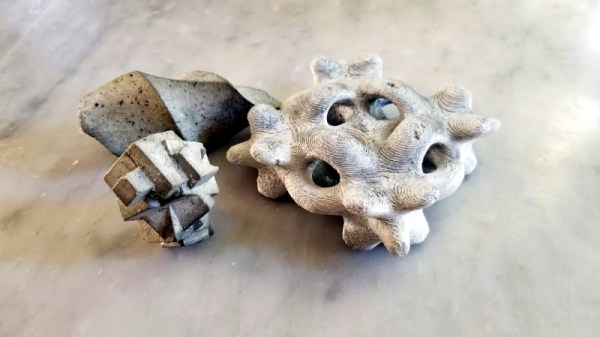
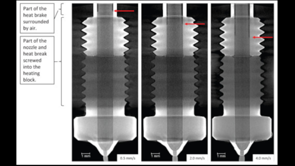
To find out, a team from the University of Stuttgart led by [Marc Kreutzbruck] took the unusual step of putting the business end of a 3D printer into a CT scanner, to get a detailed look at what’s actually going on in there. The test setup consisted of a Bondtech LGX extruder and an E3D V6 hot end mounted to a static frame. There was no need for X-Y-Z motion control during these experiments, but a load cell was added to measure extrusion force. The filament was a bit specialized — high-impact polystyrene (HIPS) mixed with a little bit of tungsten powder added (1% by volume) for better contrast to X-ray. The test system was small enough to be placed inside a micro CT scanner, which generated both 360-degree computed tomography images and 2D radiographs.

The observations made with this experimental setup were pretty eye-opening. The main take-home message is that higher filament speed translates to less contact area between the nozzle wall and the melt, thanks to an air gap between the solid filament and the metal of the nozzle. They also saw an increased tendency for the incoming filament to buckle at high extruder speeds, which matches up with practical experience. Also, filament speed is more determinative of print quality (as measured by extrusion force) than heater temperature is. Although both obviously play a role, they recommend that if higher print speed is needed, the best thing to optimize is hot end geometry, specifically an extended barrel to allow for sufficient melting time.

Earth-shattering stuff? Probably not, but it’s nice to see someone doing a systematic study on this, rather than relying on seat-of-the-pants observations. And the images are pretty cool too.

3D Printing With Multiple Soluble Filaments

Complex 3D-printed designs often require the use of an automatically generated support structure around them for stability. While this enables some truly incredible results, it adds considerable time and cost to the printing process. Plus there’s the painstaking process of removing all the support material without damaging the object itself. If you’ve got a suitably high-end 3D printer, one solution to this problem is doing the supports in a water soluble filament; just toss the print into a bath and wait for the support to dissolve away.

But what if you’re trying to print something that’s complex and also needs to be soluble? That’s precisely what [Jacob Blitzer] has been experimenting with recently. The trick is finding two filaments that can be printed at the same time but are dissolved with two different solutions. His experimentation has proved it’s possible to do with consumer-level hardware, but it isn’t easy and it’s definitely not cheap.

You might be wondering what the possible application for this technique is. For [Jacob], he wanted to be able to print hollow molds in complex geometric shapes that would ultimately be filled with concrete. The molds required extensive internal supports that would have been all but impossible to remove if they weren’t printed in a soluble filament. But he also wanted to be able to dissolve the mold once the concrete inside had cured. So he needed one easy to dissolve filament for the supports, and a harder to dissolve one for the actual mold.

For the mold itself, [Jacob] went with High Impact Polystyrene (HIPS) which can be dissolved with an industrial degreaser called Limonene. It’s expensive, and rather nasty to work with, but it does an excellent job of eating away the HIPS so that’s one problem solved. Finding a water-soluble filament for the supports that could be printed at similar temperatures to the HIPS took months of research, but eventually he found one called HyroFill that fit the bill. Unfortunately, it costs an eye-watering $175 USD per kilogram.

So you have the filaments, but what can actually print them at the same time? Multi-material 3D printing is a tricky topic, and there’s a few different approaches that have been developed over the years. In the end, [Jacob] opted to go with the FORMBOT T-Rex that uses the old-school method of having two individual hotends and extruders. It’s the simplest method conceptually, but calibrating such a machine is notoriously difficult. Running two exotic and temperamental filaments at the same time certainly doesn’t help matters.

After all the time, money, and effort put into the project (he also had to write the software that would create the 3D models in the first place) [Jacob] says he’s not exactly thrilled with the results. He’s produced some undeniably stunning pieces, but the failure rate is very high. Still, it’s fascinating research that appears to be the first of its kind, so we’re glad that he’s shared it for the benefit of the community and look forward to seeing where it goes from here.

These Gorgeous Robot Parts Are Hand-Made

[Dickel]’s robot MDi #4 has been in progress for several years, but what we wanted to draw your attention to is the way the parts have been fabricated and what kind of remarkable results are possible with careful design, measurement, cutting, and finishing. Much of MDi #4 was made by hand-cutting and drilling sheets of high impact polystyrene (HIPS) with a utility knife and layering them as needed. Epoxy and aluminum provide gap filling and reinforcement of key sections, and fiberglass took care of one of the larger sections.

The process [Dickel] follows is to prototype using cardboard first. Parts are then designed carefully in CAD, and printed out at a 1:1 scale and glued to sheets of polystyrene. Each sheet is cut and drilled by hand as necessary. Layers are stacked and epoxied, embedding any hardware needed in the process. Two examples of embedding hardware include sealing captive nuts into parts with epoxy, or using aluminum to add reinforcement. After some careful sanding, the pieces look amazing.

Scroll down a bit on that project page and you’ll see plenty of great photos of the process [Dickel] used. A video highlighting the head and a video showing the careful work that goes into making each part are embedded below.

Continue reading “These Gorgeous Robot Parts Are Hand-Made”

Adding Recycling Codes To 3D Prints

Every little plastic bauble you interact with has some sort of recycling code on it somewhere. Now that we’re producing plastic 3D printed parts at home, it would be a good idea to agree on how to recycle all those parts, and [Joshua Pearce]’s lab at Michigan Tech has the answer; since we’re printing these objects, we can just print the recycling code right in the object.

The US system of plastic recycling codes is particularly ill-suited for identifying what kind of plastic the object in question is made of; there are only seven codes, while China’s system of plastic identification uses 140 identification codes. This system for labeling 3D printed parts borrows heavily from the Chinese system, assigning ABS as ‘9’, PLA as ’92’, and HIPS as ‘108’.

With agreed upon recycling codes, the only thing left to do is to label every print with the correct recycling code. That’s an easy task with a few OpenSCAD scripts – the paper shows off a wrench made out of HIPS labeled with the correct code, and an ABS drill bit handle sporting a number nine. 3D printing opens up a few interesting manufacturing techniques, and the research team shows this off with a PLA vase with a recycle code lithophane embedded in the first few layers.

Soluble Support Structure Can Be Used With Any Extruder-based 3D Printer

One of the issues with extruder-based 3D printing is that it can be very difficult to print objects that have voids in them. You simply must have something to deposit the soft material on until it has a chance to harden. [Matt] found a solution which should work for any extruder-based printer (with one caveat we’ll get to in a minute). He prints a support structure out of HIPS then later dissolves it using Limonene. The image on the left shows the object soaking for 24 hours. The final project is seen beside it.

The only real problem with this technique is that it requires a second extruder. Since printers build objects by layers, switching material in a single print head isn’t an option. HIPS stands for High-Impact Polystyrene. It extrudes at the same temperature as the ABS (235C) and adheres well to a heated bed kept at 115C. ABS will be unaffected by the hydrocarbon solvent Limonene, except for the residual smell of citrus.