Quantum Communications In Your Browser

Quantum computing (QC) is a big topic, and last time I was only able to walk you through the construction of a few logic gates, but you have to start somewhere. If you haven’t read that part, you probably should, because you’ll need to understand the simulator I’m using and some basic concepts.

I like to get right into practice, but with this topic, there’s no avoiding some theory. But don’t despair. We’ll have a little science fiction story you can try by the end of this installment, where we manage to pack two bits of information into a single physical qubit. Last time I mentioned that qubits have 1 and 0 states and I hinted that they were really |1> and |0> states. Why create new names for the two normal binary states? Turns out there is more to the story.

What’s the Vector, Victor?

In Dirac notation, |1> is a vector. So is |hackaday> and |123>. You can get into a lot of math with these, but I’m going to try to avoid most of that. This is also called ket notation (the last part of the word bracket) so you’ll hear people say “one ket” or “hackaday ket.” Either way, the vector can represent one or more qubits and there are several ways to represent them.

Continue reading “Quantum Communications In Your Browser”

Control Thy LED

In a previous article, I discussed LEDs in general and their properties. In this write-up, I want to give some examples of driving LEDs and comparing a few of the most commonly used methods. There is no “one size fits all” but I will try and generalize as much as possible. The idea is to be able to effectively control the brightness of the LED and prolong their life while doing it. An efficient driver can make all the difference if you plan to deploy them for the long-haul. Let’s take a look at the problem and then discuss the solutions. Continue reading “Control Thy LED”

Key To Soldering: Pace Yourself

When writing my last article, I came upon something I thought had been lost to the seven seas of YouTube: the old-school “Basic Soldering Lesson” series from Pace Worldwide.

This nine-episode-long series is what retaught me to solder, and is a masterpiece, both in content and execution. With an episode titled “Integrated Circuits: T0-5 Type Packages & Other Multi-leaded Components” and a 20-minute video that only focuses on solder and flux, it’s clear from the get-go that these videos mean business. Add that to the fact that the videos are narrated by [Paul Anthony], the local weatherman in the Washington DC area back in the 80s and 90s, these videos are a joy to watch.

Even if you know what you’re doing, don’t skip the first video. It’s where the “workpiece indicator” concept, which runs throughout the series, is introduced.

Covering everything from what solder really is to how to correctly solder integrated circuits, this series has it all, even if it’s slightly dated. And, while it’s not a hack, it’s a great way to rejuvenate your soldering skills or give someone a hot start on their soldering journey.

Speaking of which, we’ve seen many things designed to educate, but one size certainly does not fit all. Do y’all know of any well-made sources that teach foundational topics that are as accessible as this series? If so, let us know in the comments.

The first video in the series is after the break. In sum, they’re long but worth it.

Continue reading “Key To Soldering: Pace Yourself”

Designing For Fab: A Heads-Up Before Designing PCBs For Professional Assembly

Designing pcbs for assembly is easy, right? We just squirt all the footprints onto a board layout, connect all the traces, send out the gerbers and position files, and we’re done–right?

Whoa, hold the phone, there, young rogue! Just like we can hack together some working source code with variables named after our best friends, we can also design our PCBs in ways that make it fairly difficult to assemble.

However, by following the agreed-upon design specs, we’ll put ourselves on track for success with automated assembly. If we want another party to put components on our boards, we need to clearly communicate the needed steps to get there. The best way to do so is by following the standards.

Proper Footprint Orientation

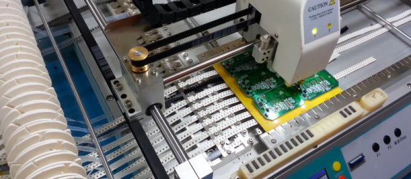
Now, for a momImage Credit: https://encrypted-tbn2.gstatic.com/images?q=tbn:ANd9GcQBEztpnSxpN_IRjq3y8GbetrMHKuoSu_s6myiFOHilL2FlQKyLrgent, let’s imagine ourselves as the tip of a vacuum pickup tool on a pick-and-place machine. These tools are designed to pick up components on the reel from their centroid and plunk them on their corresponding land pattern. Seems pretty straightforward, right? It is, provided that we design our footprints knowing that they’ll one day come face-to-face with the pick-and-place machine.

To get from the reel to the board, we, the designers, need two bits of information from out part’s datasheet: the part centroid and the reel orientation.

The part centroid is an X-Y location that calls out the center-of-mass of the part. It basically tells the machine: “pick me up from here!” As designers, it’s our responsibility to design all of our footprints such that the footprint origin is set at the part’s centroid. If we forget to do so, the pick-and-place will try to suck up our parts from a location that may not stick very well to the package, such as: the corner.

Continue reading “Designing For Fab: A Heads-Up Before Designing PCBs For Professional Assembly”

VR Mech’s Missing Link: The Phone In Your Pocket

In the process of making a homemade Mech Combat game that features robot-like piloted tanks capable of turning the cockpit independent of the direction of movement, [Florian] realized that while the concept was intuitive to humans, implementing it in a VR game had challenges. In short, when the body perceives movement but doesn’t feel the expected acceleration and momentum, motion sickness can result. A cockpit view that changes independently of forward motion exacerbates the issue.

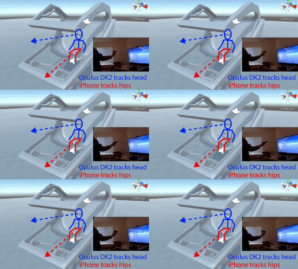
To address this, [Florian] wanted to use a swivel chair to represent turning the Mech’s “hips”. This would control direction of travel and help provide important physical feedback. He was considering a hardware encoder for the chair when he realized he already had one in his pocket: his iPhone.

By making an HTML page that accesses the smartphone’s Orientation API, no app install was needed to send the phone’s orientation to his game via a WebSocket in Unity. He physically swivels his chair to steer and is free to look around using the VR headset, separate from the direction of travel. Want to try it for yourself? Get it from [Florian]’s GitHub repository.

A video is embedded below, but if you’re interested in details be sure to also check out [Florian]’s summary of insights and methods for avoiding motion sickness in a VR Mech cockpit.

Continue reading “VR Mech’s Missing Link: The Phone In Your Pocket”

Say It With Me: Aliasing

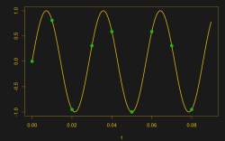
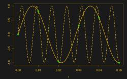
Suppose you take a few measurements of a time-varying signal. Let’s say for concreteness that you have a microcontroller that reads some voltage 100 times per second. Collecting a bunch of data points together, you plot them out — this must surely have come from a sine wave at 35 Hz, you say. Just connect up the dots with a sine wave! It’s as plain as the nose on your face.

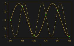
And then some spoil-sport comes along and draws in a version of your sine wave at -65 Hz, and then another at 135 Hz. And then more at -165 Hz and 235 Hz or -265 Hz and 335 Hz. And then an arbitrary number of potential sine waves that fit the very same data, all spaced apart at positive and negative integer multiples of your 100 Hz sampling frequency. Soon, your very pretty picture is looking a bit more complicated than you’d bargained for, and you have no idea which of these frequencies generated your data. It seems hopeless! You go home in tears.

But then you realize that this phenomenon gives you super powers — the power to resolve frequencies that are significantly higher than your sampling frequency. Just as the 235 Hz wave leaves an apparent 35 Hz waveform in the data when sampled at 100 Hz, a 237 Hz signal will look like 37 Hz. You can tell them apart even though they’re well beyond your ability to sample that fast. You’re pulling in information from beyond the Nyquist limit!

This essential ambiguity in sampling — that all frequencies offset by an integer multiple of the sampling frequency produce the same data — is called “aliasing”. And understanding aliasing is the first step toward really understanding sampling, and that’s the first step into the big wide world of digital signal processing.

Whether aliasing corrupts your pristine data or provides you with super powers hinges on your understanding of the effect, and maybe some judicious pre-sampling filtering, so let’s get some knowledge.

Continue reading “Say It With Me: Aliasing”

Don’t Fear The Filter: Lowpass Edition

There comes a time in every electronic designer’s life when, whether they know it or not, they need an analog filter in their design. If you’re coming from a digital background, where everything is nice and numeric, the harsh reality of continuous voltages can be a bit of a shock. But if you’re taking input from, or sending output to the big analog world out there, it pays to at least think about the frequency-domain properties of the signal, and maybe even do something about them.

Designing an analog filter to fit your needs can be a bit of a daunting task: there are many factors that you’re going to need to consider, and they all interact. It’s easy to get lost. We’re going to simplify this as much as possible by instead focusing on a few common applications and building up the simplest possible filters that work well for them.

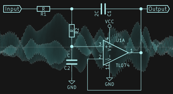
Today, we’re going to consider the lowpass filter, and specifically a Sallen-Key filter with Butterworth characteristics and a second-order rolloff. Sound like word salad? We’ll fix that up right away, because this is probably the single most important filter to have in your analog toolbox for two very common use cases: pulse-width modulated (PWM) output and analog-to-digital conversion (ADC) input.

Continue reading “Don’t Fear The Filter: Lowpass Edition”