We love a good multitool. There’s something seductive about knowing that if, for some reason, you need to saw down a tree on a moment’s notice, you have a tiny saw in your pocket. We also like electronic versions of the multitool: gadgets that serve a lot of purposes as you develop and debug hardware. One of the most polished-looking ones we’ve seen is [Phillip Schuster’s] Little Helper.
The open source gadget looks like an iPod (if an iPod had header pins sticking out of it). It has basic analog I/O capability, can generate PWM pulses, sniff I2C traffic, and do lots of other features. It is open source, so you can always add more capabilities if you need them.
There comes a time when you need to wire up three, four, or more identical i2c devices to a common microcontroller. Maybe you’re thinking about driving 128 seven-segment displays with eight of those MAX6955 16-way digit drivers, or maybe you have a robot full of joints–each of which needs a BNO055 inertial sensor for angle estimation. (See above.) Crikey! In both of those cases, you’re best bet might be a schnazzy I²C device that can do most of the work for you. The problem? With a single I²C bus, there’s no standard way defined in the protocol for connecting two or more devices with the same address. Shoot! It would’ve been handy to wire up three BNO055 IMUs or eight MAX6955s and call it a day. Luckily, there’s a workaround.
We’ve seen some clever tricks in the past for solving this problem. [Marv G‘s] method involves toggling between a device’s default and alternate address with an external pin. This method, while clever, assumes that the device (a) has an alternate I²C address and (b) features an external pin for toggling that address.
I’ll introduce two additional methods for getting the conversation started between your micro’ and your suite of identical sensors. The first is “a neat trick,” but somewhat impractical for widespread use. The second is far more production-worthy–something you could gloat over and show off to your boss! Without further ado, let’s get started with Method 1.
Lastly, if you’d like to follow along, feel free to check out the source code on Github.
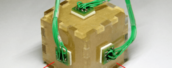
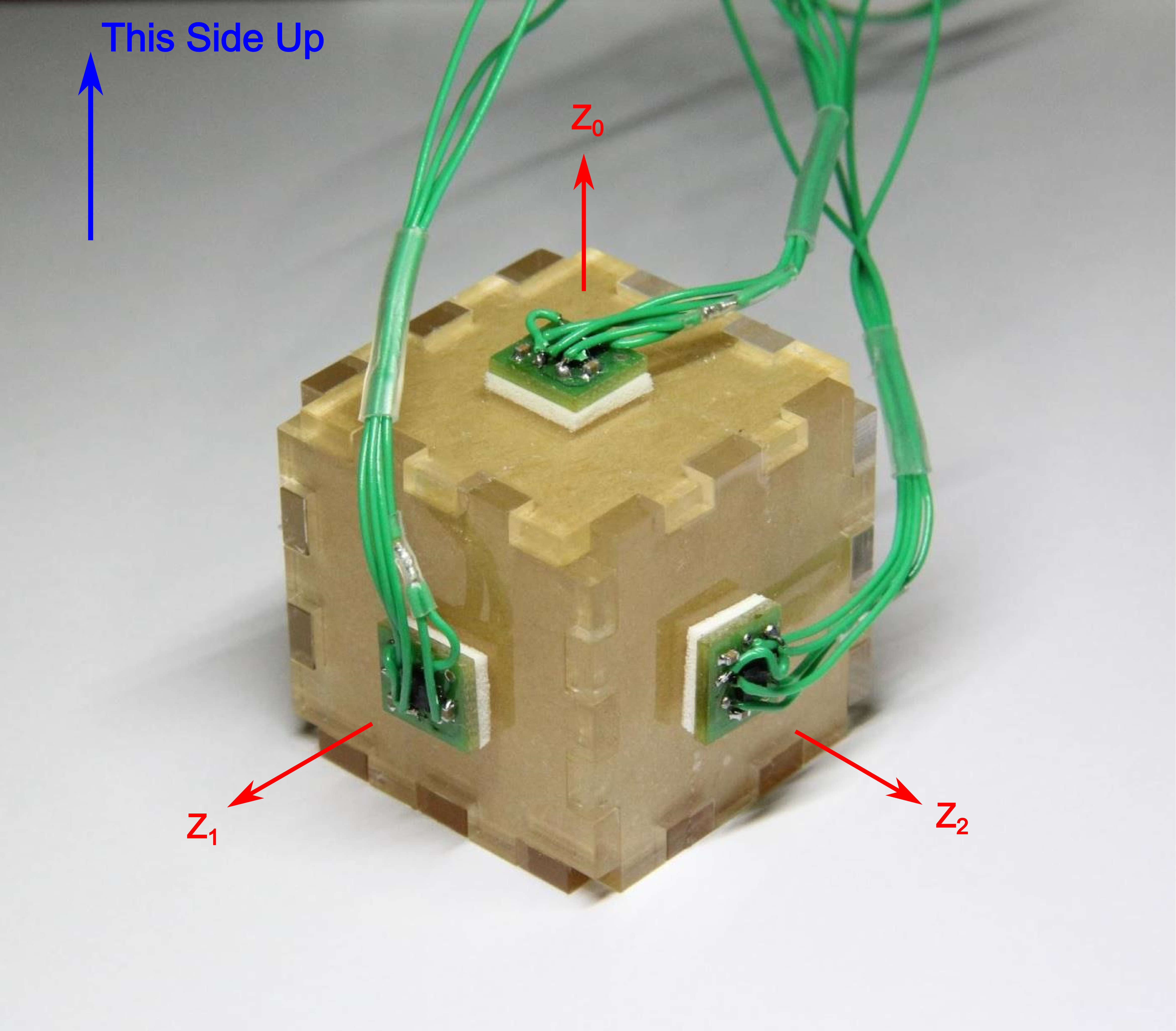
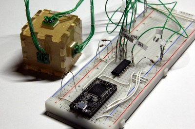
In both methods, I’m using the same sensor setup to check that each circuit behaves correctly. I happened to have a bunch of extra BMA180s on the bench, so I rolled out an example based on these chips. Back in the day, the BMA180 was a pretty common three-axis digital accelerometer. It has an I²C interface with two optional addresses. For the purpose of this example, I’m fixing them all with the same address. I’ve mounted three of these guys on mutually perpendicular axes of my acrylic “test cube,” and I’m reading each chip’s Z-axis. In this configuration I can easily pick out the gravity vector from the corresponding sensor as the data goes flying by my serial port window. If I can uniquely address each sensor and read the data, I’ve got a working circuit.
Method 1: Splicing Clocks into Chip-Selects
This method tips its hat towards SPI in that it behaves in an oddly similar fashion. If you’re feeling rusty on SPI, here’s a quick recap.
A Quick SPI Refreshment:
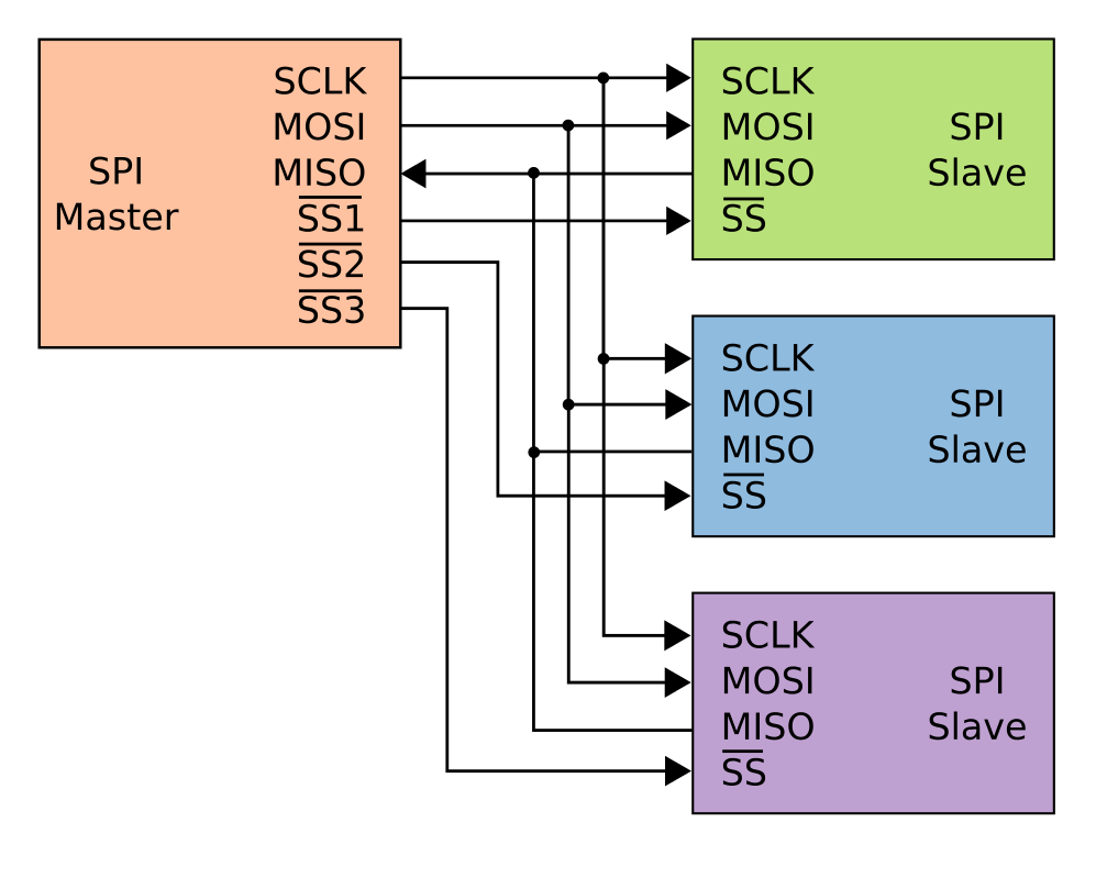
SPI, like I²C, is another protocol that shares both its clock and data lines with multiple slave devices. The difference, though, lies in the addressing scheme to talk to these devices that share the same bus. With SPI, while clock and data lines are shared, devices are addressed with separate chip-select (CS) lines.
The master microcontroller dedicates a unique output pin to each device (~SS1, ~SS2, and ~SS3 in this illustration). When the master micro’ wants to talk to a device, it asserts that device’s chip-select input pin by pulling it to logic LOW, and the conversation begins over the data bus. With the chip select LOW, the corresponding slave listens to the data on the bus. Meanwhile, all other devices ignore the conversation between the master and it’s chosen slave by keeping their bus pins in a high impedance state.
Giving I²C Its Own Chip-Selects:
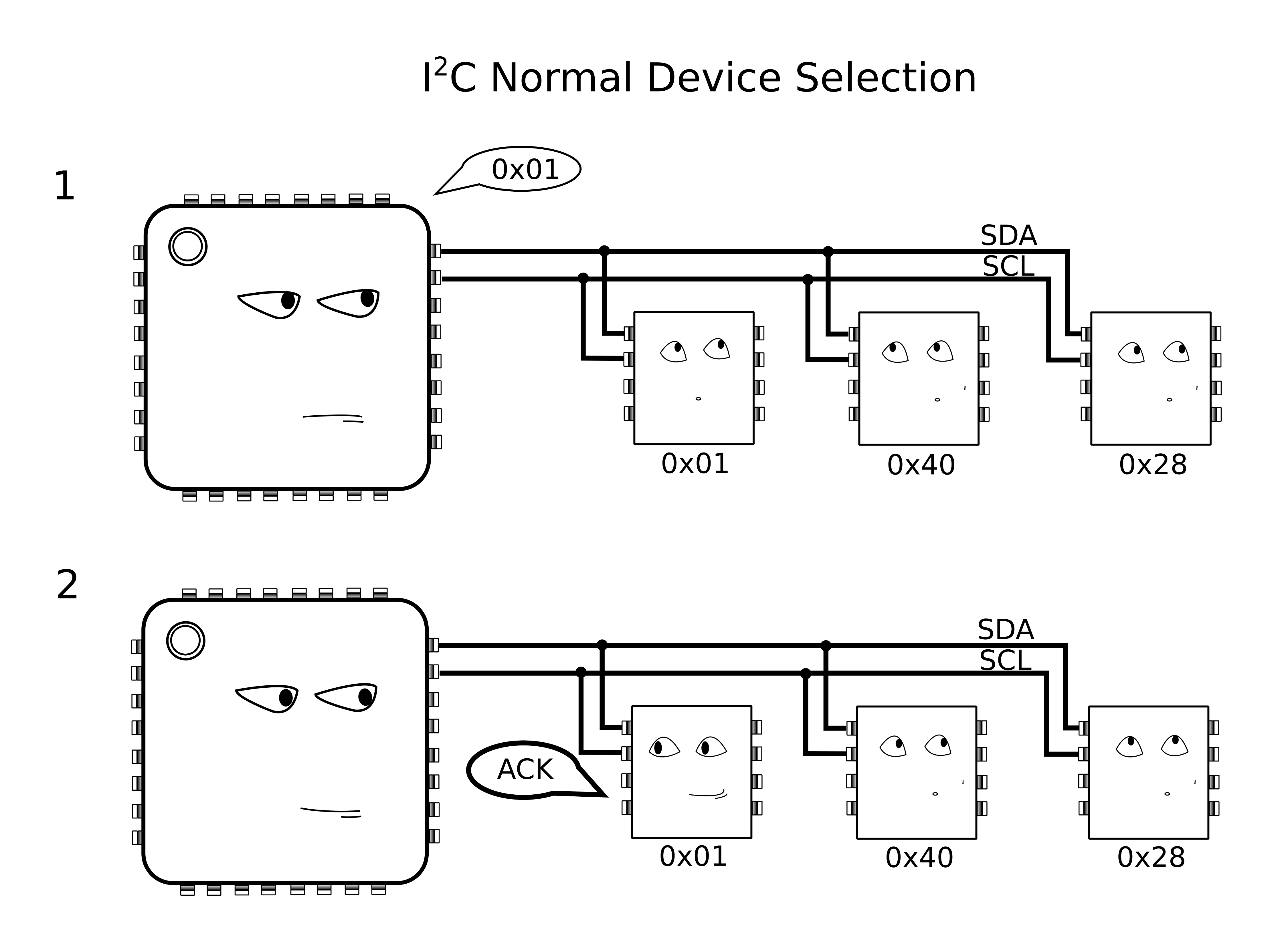
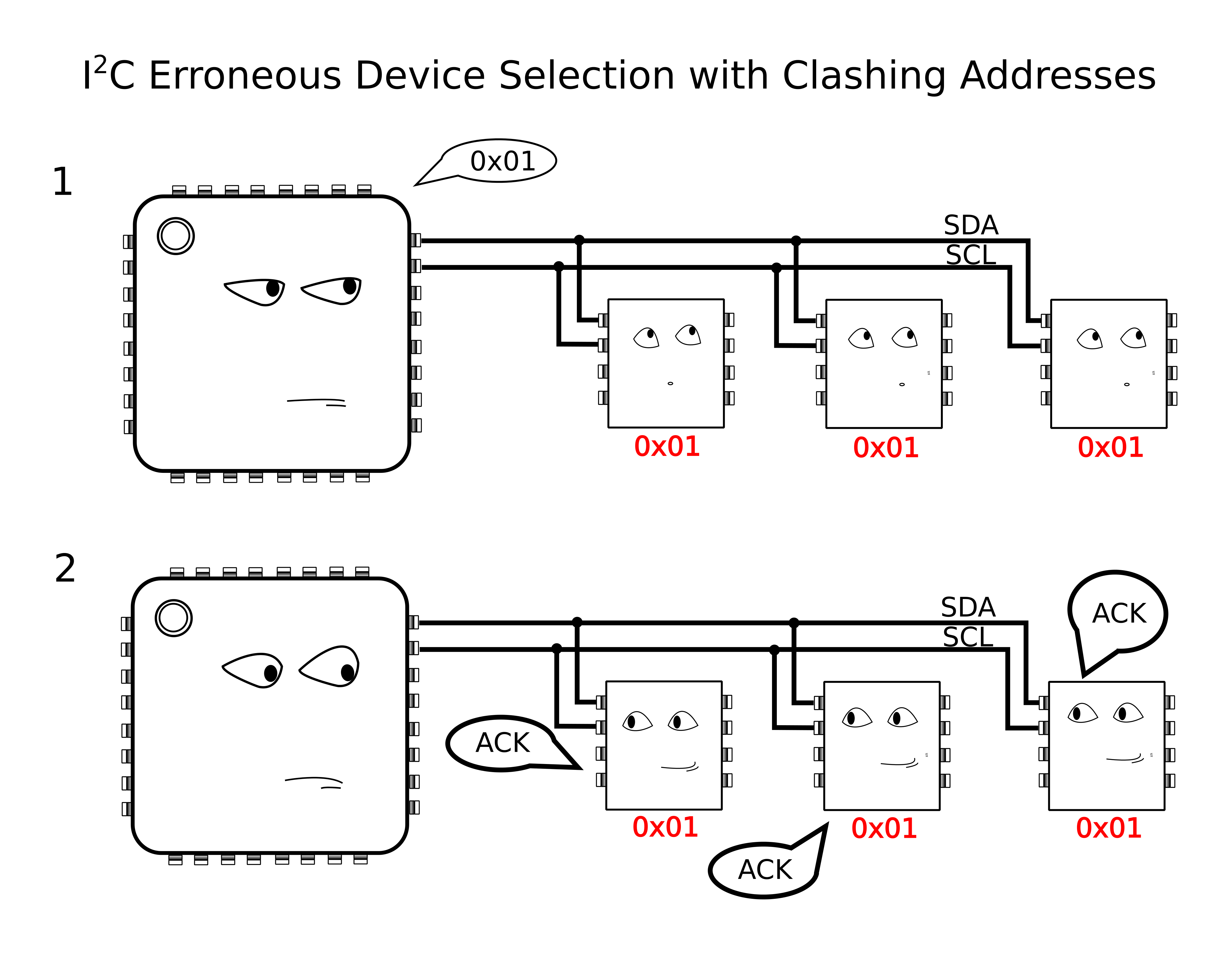
With I²C, Clock (SCL) and Data (SDA) lines are still shared between all I2C slave devices, but the addressing scheme happens by sending a message heard by all devices on the bus. To single out one device on the shared bus, the master first passes down the address of the slave device it wants to talk to, after which that slave replies with an ACKnowledge, and all other slaves ignore the data that follows until both data transmission is complete and the bus is “released.”
Because we have the problem of multiple devices with shared addresses, in theory, all of these devices would reply when the master passes down their shared address, and there’s no way for the master to single out a single device. In reality, this behavior is undefined on the I²C protocol.
Yikes! Anything goes when we wander away from defined behavior, so we try to avoid these things in practice.
The solution?
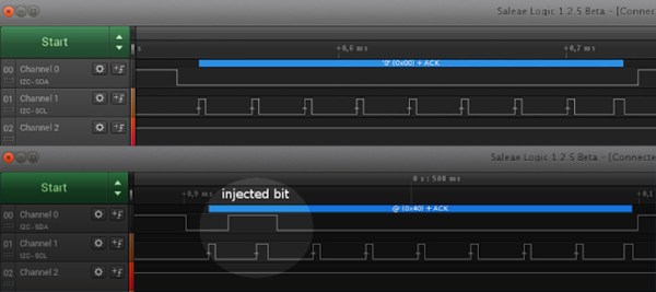
According to the I²C spec, It just so happens that an I²C slave device will ignore changes on the data line (SDA) provided that the clock line (SCL) is held high. In this method, I’ll “split” the SCL line into multiple SCL lines such that each shared I²C device gets its own SCL. By selectively rerouting the clock to each I²C device one-at-a-time, I’ve essentially turned the SCL line into a “chip select.”
To chop up that clock line, I’ll need a demultiplexer. A demultiplexer (or decoder) takes a logical input and reroutes it to one of several outputs based on the binary select lines.
I’ve dropped in the 74AC11138 eight-way demultiplexer for this task. It’s fast, capable of switching at megahertz rates, and its outputs default to logic HIGH. That second note is handy since idle SCL lines also default to logic HIGH.
The setup is shown in a simplified schematic above. In it, I’m using a Teensy 3.0 posing as the I²C bus master. To the right of the Teensy is the collection of identical chips, BMA180 accelerometers in this case. In the middle is the 74AC11138 eight-way demultiplexer.
Cons of this Method:
There’s a minor drawback with this technique, though, in that it doesn’t support I²C’s clock-stretching feature. Taking a step back, this method assumes that the SCL line is inherently unidirectional, controlled by only the I²C bus master. In other words, we’re making the assumption that data on the SCL line is only sent from master to slave and never the other way around. If your I²C slave devices implement clock-stretching, however, this assumption breaks down.
What is Clock Stretching?
Clock stretching is a method defined by the I²C protocol where the chip needs to “buy itself more time” and holds the SCL line low, hence, signalling to the master that it’s not ready for the upcoming data. In this scenario, the slave actively controls the SCL line, and it happens to be the only case where data moves up the SCL line from slave to master. In a setup with our demultiplexer between the master and our set of identical slaves, these slaves won’t be able to send back the clock-stretching signal to the master to indicate that they aren’t ready for data, if they happen to implement clock stretching. That said, clock stretching is a pretty rare feature among I²C-compatible devices, so this method is likely to work among a number of chips out now.
More Next Week
That’s all for Method 1. Thanks for tuning in, and check back next week for a slightly-more-professional method of tackling this same problem.
When an air quality display project needed a display, [Inderpreet] looked into small character-based LCDs. [Inderpreet’s] chosen LCD used an I2C interface, which was new to him. Rather than shy away, [Inderpreet] grabbed his Bus Pirate and dove in!
I2C or Inter-Integrated Circuit serial interfaces are often mentioned here on Hackaday. They generally are easy to use, but as with all things, there are little gotchas which can make the road a bit more bumpy the first time you travel it. One of those things is voltage interfacing – I2C uses bidirectional open drain lines, so interfacing 3.3 V and 5V circuits requires a voltage level shifter circuit designed to handle that requirement. Thankfully in [Inderpreet’s] case, both his TI launchpad target devboard and the LCD used 3.3 volt logic levels.
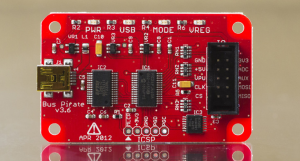
Before using the TI though, [Inderpreet] wanted to test with the Bus Pirate first. This would allow him to verify the hardware, and to make sure he was correctly using the I2C bus. The Bus Pirate can operate at 3.3V or 5V logic levels, and has on-board programming specific to the I2C bus. Controlling the Bus Pirate is as easy as hooking up a serial terminal program and plugging in a USB cable.
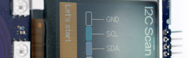
The I2C bus protocol is relatively simple, but can still be confusing to a new user. Each transaction needs an address, read/write bit, and a start command sent in the proper sequence before the data bytes can begin flowing. There are also acknowledge bits which prove that the data bytes are actually being received by the LCD. The Bus Pirate made all this easy, allowing [Inderpreet] to quickly display “Hello” on his LCD module.
The I2C bus is just the tip of the iceberg for the Bus Pirate. If you’re interested in learning more, check it out over at The Hackaday Store!
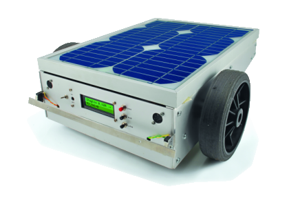
It takes a lot of power and energy to keep grass levels down to an appropriate level; especially when it’s hot out. If cool glasses of lemonade aren’t around, the task at hand may not be completed any time soon causing the unkempt blades of green (or yellow) vegetation outside to continue their path of growth towards the sun.
Instead of braving the oven-like temperatures which will inevitably drench the person in sweat, this solar powered robot has been created ready to take on the job. With the heart of an Arduino, this device shaves down the grass on a regular basis, rather than only chopping down the material when it gets too long. This helps to save electricity since the mower is only dealing with young and soft plants whose heads are easily lopped off without much effort.
Internally, the robot’s circuitry interfaces with an underground wiring system that defines the cutting zones within the lawn, and proves to be a simple, accurate, and reliable approach to directing the robot where to go. If the device travels under a shaded area, a battery kicks in supplying energy to the engine. When sunlight is available, that same battery accumulates the electricity, storing it for later.
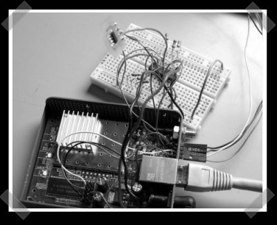
La Fonera’s are getting pretty popular lately. [Lefinnois] hacked his to get i2c working. He used a 75LS05 to adapt the io levels, and some bit banging in the software to pull it off. Now the Fonera can be used for inexpensive remote monitoring via inexpensive i2c devices. Not to mention that this could provide a cheap network interface for various micro-controller projects. (I’m thinking networked thermostat for my new house.)


 I’ve dropped in the 74AC11138 eight-way demultiplexer for this task. It’s fast, capable of switching at megahertz rates, and its outputs default to logic HIGH. That second note is handy since idle SCL lines also default to logic HIGH.
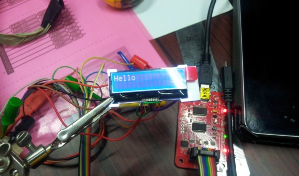
 Before using the TI though, [Inderpreet] wanted to test with the Bus Pirate first. This would allow him to verify the hardware, and to make sure he was correctly using the I2C bus. The Bus Pirate can operate at 3.3V or 5V logic levels, and has on-board programming specific to the I2C bus. Controlling the Bus Pirate is as easy as hooking up a serial terminal program and plugging in a USB cable.