Bare-Metal STM32: Using The I2C Bus In Master-Transceiver Mode

As one of the most popular buses today for on- and inter-board communication within systems, there’s a good chance you’ll end up using it with an embedded system. I2C offers a variety of speeds while requiring only two wires (clock and data), which makes it significantly easier to handle than alternatives, such as SPI. Within the STM32 family of MCUs, you will find at least one I2C peripheral on each device.

As a shared, half-duplex medium, I2C uses a rather straightforward call-and-response design, where one device controls the clock, and other devices simply wait and listen until their fixed address is sent on the I2C bus. While configuring an STM32 I2C peripheral entails a few steps, it is quite painless to use afterwards, as we will see in this article. Continue reading “Bare-Metal STM32: Using The I2C Bus In Master-Transceiver Mode”

Four jumper wires with white heatshrink on them, labelled VCC, SCL, SDA and GND

The Connector Zoo: I2C Ecosystems

I2C is a wonderful interface. With four wires and only two GPIOs, you can connect a whole lot of sensors and devices – in parallel, at that! You will see I2C used basically everywhere, in every phone, laptop, desktop, and any device with more than a few ICs inside of it – and most microcontrollers have I2C support baked into their hardware. As a result, there’s a myriad of interesting and useful devices you can use I2C with. Occasionally, maker-facing companies create plug-and-play interfaces for the I2C device breakouts they produce, with standardized pinouts and connectors.

Following a standard pinout is way better than inventing your own, and your experience with inconsistent pin header pinouts on generic I2C modules from China will surely reflect that. Wouldn’t it be wonderful if you could just plug a single I2C-carrying connector into an MPU9050, MLX90614 or HMC5883L breakout you bought for a few dollars, as opposed to the usual hurdle of looking at the module’s silkscreen, soldering pin headers onto it and carefully arranging female headers onto the correct pins?

As with any standard, when it comes to I2C-on-a-connector conventions, you would correctly guess that there’s more than one, and they all have their pros and cons. There aren’t quite fifteen, but there’s definitely six-and-a-half! They’re mostly inter-compatible, and making use of them means that you can access some pretty powerful peripherals easily. Let’s start with the two ecosystems that only have minor differences, and that you’ll encounter the most! Continue reading “The Connector Zoo: I2C Ecosystems”

Screenshot of a logic analyzer software, showing the SDA channel being split into three separate traces

I2C Tap Helps Assign Blame For SDA Conflicts

If you’ve ever debugged a misbehaving I2C circuit, you probably know how frustrating it can be. Thankfully [Jim] over at Hackaday.io, has a proto-boardable circuit that can help!

Inter-integrated circuit bus (aka I2C) uses open collector outputs on a two wire interface. Open collector means a device connected to the I2C bus can only pull the bus down to ground. Chips never drive a logic “HIGH” on the wires. When nothing is driving the lines low, a weak resistor pulls the lines up to VCC. This is a good thing, because I2C is also a multidrop bus — meaning many devices can be connected to the bus at the time. Without open collector outputs, one chip could drive a high, while another drives a low – which would create a short circuit, possibly damaging both devices.

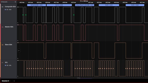
Even with all this protection, there can be problems. The SCL and SDA lines in the I2C communication protocol are bidirectional, which means either a controller or a peripheral can pull it low. Sometimes, when tracing I2C communications you’ll need to figure out which part is holding the line low. With many devices sharing the same bus, that can become nigh-impossible. Some folks have tricks with resistors and analog sampling, but the tried and true method of de-soldering and physically lifting chip pins off the bus often comes into play.

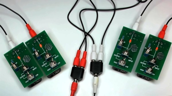
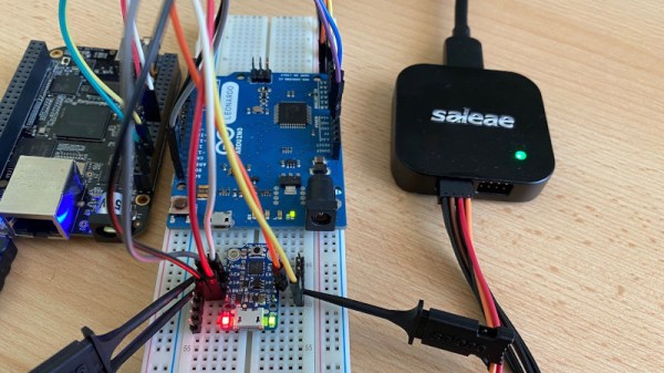
[Jim’s] circuit splits SDA signal into controller-side and peripheral-side, helping you make it clear who is to blame for hiccups and stray noise. To do that, he’s using 6N137 optoisolators and LMV393 comparators. [Jim] shared a NapkinCAD schematic with us, meant to be replicate-able in times of dire need. With this design, you can split your I2C bus into four separate channels – controller-side SDA, peripheral-side SDA, combined SDA and SCL. 4 Channels might be a lot for a scope, but this is no problem for today’s cheap logic analyzers.

Continue reading “I2C Tap Helps Assign Blame For SDA Conflicts”

Two pairs of boards described in the article, with toggle switches and RCA jacks, shown interconnected, LEDs on all four boards lit up.

Boards For Playful Exploration Of Digital Protocols

Teaching people efficiently isn’t limited to transmitting material from one head to another — it’s also about conveying the principles that got us there. [Mara Bos] shows us a toolkit (Twitter,
nitter link
) that you can arm your students with, creating a small playground where, given a set of constraints, they can invent and figure communication protocols out on their own.

This tool is aimed to teach digital communication protocols from a different direction. We all know that UART, I2C, SPI and such have different use cases, but why? Why are baud rates important? When are clock or chip select lines useful? What’s the deal with the start bit? We kinda sorta figure out the answers to these on our own by mental reverse-engineering, but these things can be taught better, and [Mara] shows us how.

Gently guided by your observations and insights, your students will go through defining new and old communication standards from the ground up, rediscovering concepts like acknowledge bits, bus contention, or even DDR. And, as you point out that the tricks they just discovered have real-world counterparts, you will see the light bulb go on in their head — realizing that they, too, could be part of the next generation of engineers that design the technologies of tomorrow.

Continue reading “Boards For Playful Exploration Of Digital Protocols”

The Virtue Of Wires In The Age Of Wireless

We ran an article this week about RS-485, a noise resistant differential serial multidrop bus architecture. (Tell me where else you’re going to read articles like that!) I’ve had my fun with RS-485 in the past, and reading this piece reminded me of those days.

You see, RS-485 lets you connect a whole slew of devices up to a single bundle of Cat5 cable, and if you combine it with the Modbus protocol, you can have them work together in a network. Dedicate a couple of those Cat5 lines to power, and it’s the perfect recipe for a home, or hackerspace, small-device network — the kind of things that you, and I, would do with WiFi and an ESP8266 today.

Wired is more reliable, has fewer moving parts, and can solve the “how do I get power to these things” problem. It’s intrinsically simpler: no radios, just serial data running as voltage over wires. But nobody likes running cable, and there’s just so much more demo code out there for an ESP solution. There’s an undeniable ease of development and cross-device compatibility with WiFi. Your devices can speak directly to a computer, or to the whole Internet. And that’s been the death of wired.

Still, some part of me admires the purpose-built simplicity and the bombproof nature of the wired bus. It feels somehow retro, but maybe I’ll break out some old Cat5 and run it around the office just for old times’ sake.

A Gaggle Of Boards Makes For An I2C Playground

It’s not much of a stretch to assume that the majority of Hackaday readers are at least familiar with I2C. In fact, there’s an excellent chance that anyone who’s ever done more with an Arduino than blink the onboard LED has at one time or another used the serial communication protocol to talk to a sensor, display, or other external gadget. Of course, just because most of us have used it in a few projects doesn’t mean we truly understand it.

If you’re looking to brush up on your I2C knowledge, you could do worse than to follow the guide [András Tevesz] recently wrote up. With a title like Hardware Hacking 101: E01 I2C Sniffing, How to Listen to Your Arduino’s I2C Bus, you know you’re in for a good time. While the document is arguably geared more towards security researchers than electronic hobbyists, the concepts presented can be useful even if you’re just trying to debug your own projects. Continue reading “A Gaggle Of Boards Makes For An I2C Playground”

Quick-Swap Socket For Stemma QT Experiments

[kmatch98] shares a quick hack with us over at Hackaday.io – a 3D-printed socket for Adafruit Stemma QT-based I2C modules. Since Adafruit has standardized the dimensions for their Stemma QT boards, it’s possible to make a socket that would fit many different sensors at once, where the board just slides in.

This reminds us of sci-fi datadisks, or, thinking of something more grounded in reality, game console cartridges – except that here, the fun you’re having is from exploring all the different devices you can get to speak I2C. To make such a socket, you only need to 3D-print two plastic parts, put a JST-SH plug between them, and screw them together – if you want to modify these to your liking, .f3d sources are available. Now you no longer have to use fingernails or tin snips to take the JST-SH plug out of your modules!

[kmatch98] is no stranger to sharing his projects on Hackaday.io with us, and we’ve covered some of his larger projects before, like this CircuitPython-powered cyber-duck cyberdeck, or the 3D-printable Maypole braider machine!