The $50 Ham: A Cheap Antenna For The HF Bands

So far in the $50 Ham series, I’ve concentrated mainly on the VHF and UHF bands. The reason for this has to do mainly with FCC rules, which largely restrict Technician-level licensees to those bands. But there’s a financial component to it, too; high-frequency (HF) band privileges come both at the price of learning enough about radio to pass the General license test, as well as the need for gear that can be orders of magnitude more expensive than a $30 handy-talkie radio.

But while HF gear can be expensive, not everything needed to get on the air has to be so. And since it’s often the antenna that makes or breaks an amateur radio operator’s ability to make contacts, we’ll look at a simple but versatile antenna design that can be adapted to support everything from a big, powerful base station to portable QRP (low-power) activations in the field: the end-fed half-wave antenna.

Continue reading “The $50 Ham: A Cheap Antenna For The HF Bands”

Dead Simple Time-Domain Reflectometry With Just A Battery And An Oscilloscope

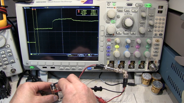
“Time-domain reflectometry” sure sounds like something that needs racks of expensive equipment to accomplish. In reality, TDR is just measuring the time between injecting a pulse into a cable and receiving its echo, either from the other end of the cable or from some fault or defect along the way. It’s a useful technique, and as [Allen Wolke (W2AEW)] shows us, it can be accomplished with little more than a battery, a resistor, and an oscilloscope. And a little math, of course.

There are, of course, dedicated time-domain reflectometers, but all of them are really just elaborations of the basic principles [W2AEW] demonstrates with his simple setup. The oscilloscope is set up with a tee connector on one channel; one side of the tee is connected to the cable under test, while the shield conductor of the other side is connected to the negative terminal of a 9V battery. A resistor connected to the center conductor is used to complete the circuit, which sends a brief pulse down the test cable. The scope is set up to capture the outgoing pulse as well as the return pulse, allowing the time between the two to be measured. Some simple math gives the length of the cable, the distance to a fault, or with a little rearrangement, the velocity factor of the cable.

The video below shows the simple method at work on coax and Cat 5e Ethernet cable. It even worked on a roll of zip cable, which was a little surprising. If this technique is too simple, you can always elaborate a bit and roll your own TDR tester. Googly eyes optional, of course, but recommended.

Continue reading “Dead Simple Time-Domain Reflectometry With Just A Battery And An Oscilloscope”

Finding RF Cable Impedance

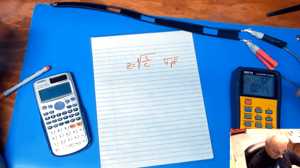
At DC and low frequency, we can pretend wires are perfect conductors. At radio frequencies, though, there are many effects that you need to take into account for wires and cables. One of these is characteristic impedance. If you have a marked cable, you can look it up on the Internet, of course. But what if you don’t know what kind of wire it is? With help from [The Offset Volt], you can measure it as he shows in the video below.

This is one of those things that used to take exotic test equipment like an LCR bridge, but these days meters that measure inductance and capacitance are commonplace. The trick is simple: measure the capacitance and then short one end of the cable and measure the inductance.

Continue reading “Finding RF Cable Impedance”

Shoot The Moon With This Homebrew Hardline RF Divider

You can say one thing for [Derek]’s amateur radio ambitions — he certainly jumps in with both feet. While most hams never even attempt to “shoot the Moon”, he’s building out an Earth-Moon-Earth, or EME, setup which requires this little beauty: a homebrew quarter-wave hardline RF divider, and he’s sharing the build with us.

For background, EME is a propagation technique using our natural satellite as a passive communications satellite. Powerful, directional signals can bounce off the Moon and back down to Earth, potentially putting your signal in range of anyone who has a view of the Moon at that moment. The loss over the approximately 770,000-km path length is substantial, enough so that receiving stations generally use arrays of high-gain Yagi antennas.

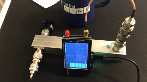
That’s where [Derek]’s hardline build comes in. The divider acts as an impedance transformer and matches two 50-ohm antennas in parallel with the 50-ohm load expected by the transceiver. He built his from extruded aluminum tubing as the outer shield, with a center conductor of brass tubing and air dielectric. He walks through all the calculations; stock size tubing was good enough to get into the ballpark for the correct impedance over a quarter-wavelength section of hardline at the desired 432-MHz, which is in the middle of the 70-cm amateur band. Sadly, though, a scan of the finished product with a NanoVNA revealed that the divider is resonant much further up the band, for reasons unknown.

[Derek] is still diagnosing, and we’ll be keen to see what he comes up with, but for now, at least we’ve learned a bit about homebrew hardlines and EME. Want a bit more information on Moon bounce? We’ve got you covered.

Continue reading “Shoot The Moon With This Homebrew Hardline RF Divider”

Complex Impedances Without The Pain

Any grizzled electronic engineer will tell you that RF work is hard. Maintaining impedance matching may be a case of cutting wires to length at lower frequencies, but into the low centimetre and millimetre wavelengths it becomes a Dark Art aided by mysterious and hugely expensive test equipment beyond the reach of mere mortals. A vector network analyser or VNA may be beyond the reach of many, but [Tomasz WÄ…torowski] is here to tell us about how with some resistors, mathematics, and a bit of lateral thinking its functions may be replicated with a more modestly equipped bench.

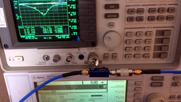
It’s not a method for the faint-hearted as the mathematics are of the variety that you probably learned as an undergraduate but let slip from your memory with thanks after the course ended. The method involves measuring the return loss both with and without a resistor of known value in series with the antenna, these figures allow the real and imaginary components of the antenna’s impedance to be calculated. There is a further piece of work though, this method doesn’t determine whether the antenna is capacitive or inductive. Repeating the measurement with either a capacitive or inductive matching network allows this to be determined, and the value of the appropriate matching component to be calculated.

If you are interested in this kind of work, start with a primer on RF design.

Complex impedance matching using scalar measurements, math and resistors

The $50 Ham: Dummy Loads, Part 2

In the last installment of “The $50 Ham” I built a common tool used by amateur radio operators who are doing any kind of tuning or testing of transmitters: a dummy load. That build resulted in “L’il Dummy”, a small dummy load intended for testing typical VHF-UHF handy talkie (HT) transceivers, screwing directly into the antenna jack on the radio.

As mentioned in the comments by some readers, L’il Dummy has little real utility. There’s actually not much call for a dummy load that screws right into an HT, and it was pointed out that a proper dummy load is commercially available on the cheap. I think the latter observation is missing the point of homebrewing specifically and the Hackaday ethos in general, but I will concede the former point. That’s why at the same time I was building L’il Dummy, I was building the bigger, somewhat more capable version described here: Big Dummy.

Continue reading “The $50 Ham: Dummy Loads, Part 2”

The $50 Ham: Dummy Loads

This is an exciting day for me — we finally get to build some ham radio gear! To me, building gear is the big attraction of amateur radio as a hobby. Sure, it’s cool to buy a radio, even a cheap one, and be able to hit a repeater that you think is unreachable. Or on the other end of the money spectrum, using a Yaesu or Kenwood HF rig with a linear amp and big beam antenna to work someone in Antartica must be pretty cool, too. But neither of those feats require much in the way of electronics knowledge or skill, and at the end of the day, that’s why I got into amateur radio in the first place — to learn more about electronics.

To get my homebrewer’s feet wet, I chose perhaps the simplest of ham radio projects: dummy loads. Every ham eventually needs a dummy load, which is basically a circuit that looks like an antenna to a transmitter but dissipates the energy as heat instead of radiating it an appreciable distance. They allow operators to test gear and make adjustments while staying legal on emission. Al Williams covered the basics of dummy loads a few years back in case you need a little more background.

We’ll be building two dummy loads: a lower-power one specifically for my handy talkies (HTs) will be the subject of this article, while a bigger, oil-filled “cantenna” load for use with higher power transmitters will follow. Neither of my designs is original, of course; borrowing circuits from other hams is expected, after all. But I did put my own twist on each, and you should do the same thing. These builds are covered in depth on my Hackaday.io page, but join me below for the gist on a good one: the L’il Dummy.

Continue reading “The $50 Ham: Dummy Loads”