Building Reaction Wheels With Python And LEGO

Reaction wheels are useful things, typically used by satellites to keep themselves oriented the right way up in space. Turning the reaction wheel creates an equal and opposite torque in the spacecraft, allowing it to point and rotate itself accurately. The same technique also works here on Earth, and [Brick Experiment Channel] decided to build one out of LEGO to control an inverted pendulum.

The initial design using a small LEGO wheel on an inverted pendulum was only able to work reliably over a 4-degree angle from the vertical. Upgrading the wheel to a larger, heavier one enabled the wheel to instead work over a 28-degree range instead.

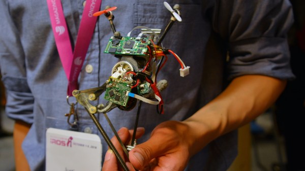
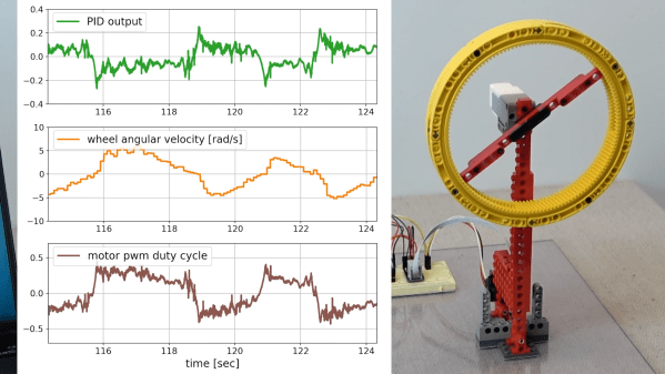
A MPU9250 inertial measurement unit was pressed into service for control of the reaction wheel, fitted to the base of the pendulum and read by a Raspberry Pi. The Pi takes accelerometer and gyroscope readings, and then controls the motor on the pendulum with a PID controller to keep the inverted pendulum upright.

The video goes into a great deal of detail on what it takes to make the pendulum run smoothly. From changes to the control coefficients to measuring the motor’s back EMF, [Brick Experiment Channel] demonstrates everything required to make the pendulum robust to outside perturbances.

The inverted pendulum is a great way to learn about control theory, as we’ve seen time and again.

Continue reading “Building Reaction Wheels With Python And LEGO”

Inverted Pendulum Balanced On A Drone

[Nicholas Rehm] works during the day at the Applied Physics Laboratory at Johns Hopkins, Maryland, so has considerable experience with a variety of UAV applications. The question arose about how the perseverance mars rover landing worked, which prompted [Nicholas] to hang a rock under his drone, attached via a winch. This proved to be interesting. But what is more interesting for us, is what happens when you try to attach an inverted pendulum to the top of a drone in flight? (video embedded, below)

This is a classic control theory problem, where you need to measure the angle of the pendulum with respect to the base, and close the loop by calculating the necessary acceleration from the pendulum angle. Typically this is demonstrated in one dimension only, but it is only a little more complicated to balance a pendulum with two degrees of freedom.

[Nicholas] first tried to derive the pendulum angle by simply removing the centering springs from an analog joystick, and using it to attach the pendulum rod to the drone body. As is quite obvious, this has a big drawback. The pendulum angle from vertical is now the sum of the joystick angle and the drone angle, which with the associated measurement errors, proved to be an unusable setup. Not to be discouraged, [Nicholas] simply added another IMU board to the bottom of the pendulum, and kept the joystick mechanism as a pivot only. And, as you can see from the video after the break, this indeed worked.

The flight controller is [Nicholas’] own project, dRehmFlight (GitHub), which is an Arduino library intended for the Teensy 4.0, using the ubiquitous MPU6050 6-DOF IMU. [Nicholas] also made an intro video for the controller, which may prove instructive for those wishing to go down this road to build their own VTOL aircraft. The code for pendulum experiment is not available at the time of writing, perhaps it will hit the GitHub in the future?

Continue reading “Inverted Pendulum Balanced On A Drone”

Bobble-Bot Teaches Modern Real-Time Robot Control

Bobble-Bot uses the standard inverted pendulum problem to teach modern robotic control using a Raspberry Pi, RT-Linux, and ROS.

We’re really impressed by the polish and design effort put into this project, and it’s no surprise that it’s a finalist in the 2019 Hackaday Prize. Bobble-Bot is a top heavy bot sitting on two BLDC motors. The brains of the operation is a Raspberry Pi running real-time Linux and ROS. This allows the robot to respond in a predictable manner to its inputs, and also allows for more control over thread priority than a regular kernel. In the past we’ve seen these inverted pendulum bots mostly being run on micro-controllers for just this reason, so it’s cool to see it make the jump to Linux.

Mechanically the bot can be printed on any consumer grade printer and assembled. We really appreciate the small details like making sure one screw size could be used to assemble the entire bot, eliminating the need for multiple tools.

They also have a simulator, and the bot’s software was built inside of that. It was a big moment when the real-world behavior finally matched the simulated performance. In fact, if you’re interested in the Bobble-Bot, you can try it out in simulation before committing to building the whole thing.

This project seems like a fun build for any hacker. We would have loved to have a project as polished and up-to-date as this one when we were learning controls in university. Video introducing it after the break.


One-Legged Jumping Robot Shows That Control Is Everything

Robots that can jump have been seen before, but a robot that jumps all the time is a little different. Salto-1P is a one-legged jumping robot at UC Berkeley, and back in 2017 it demonstrated the ability to hop continuously with enough control to keep itself balanced. Since then it has been taught some new tricks; having moved beyond basic stability it can now jump around and upon things with an impressive degree of control.

Key to doing this is the ability to plant its single foot exactly where it wants, which allows for more complex behaviors such as hopping onto and across different objects. [Justin Yim] shows this off in the video embedded below, which demonstrates the Salto-1P bouncing around in a remarkably controlled fashion, even on non-ideal things like canted surfaces. Two small propellers allow the robot to twist in midair, but all the motive force comes from the single leg.

Continue reading “One-Legged Jumping Robot Shows That Control Is Everything”

EddiePlus, The Edison Based Balancing Robot

[Renee] dropped a tip to let us know about EddiePlus, her balancing robot creation. As its name might imply, EddiePlus is controlled by an Intel Edison processor. More specifically, [Renee] is using several of Sparkfun’s Edison Blocks to create Eddie’s brain. EddiePlus’ body is 3D printed, while his movement comes from two Pololu DC motors with wheels and encoders. The full build instructions are available as a PDF from [Renee’s] Google drive.

Eddie is able to balance and drive around on two wheels, much like a Segway. Sensor data for balance comes from Sparkfun’s LSM9DS0 based Inertial Measurement Unit (IMU) block. In this new “plus” version of Eddie, [Renee] has added encoders to the robot’s wheels. This makes it easier for him to adapt to changing loads – such as pumping iron (or banana plugs as the case may be). The encoders also help with varying terrain, as [Renee] demonstrates by tilting a board as Eddie drives on it. Eddie’s code is written in C, and available on Github.  Controlling Eddie is as easy as sending simple commands via UDP.

As you might imagine, the Intel Edison still has plenty of cycles left over after computing Eddie’s balance. [Renee] uses some of these with a webcam based teleoperation mode.

Click past the break to see Eddie in action!

Continue reading “EddiePlus, The Edison Based Balancing Robot”

PIDDYBOT – A Self Balancing Teaching Tool

We’re sure that most Hackaday readers are already familiar with the inverted pendulum system, which basically consists of a pendulum having its center of mass above its pivot point. Most applications (like the one we are going to describe) limit the pendulum to 1 degree of freedom by affixing the pole (or circuit board here) to an axis of rotation. The overall system is therefore inherently unstable and must be actively balanced in order to remain upright.

[Sean] created the piddybot, a tiny balancing robot aimed to teach the basics of PID control by trying to get the robot to stand still. More interestingly, the Proportional / Integral / Derivative values can directly be adjusted using the three on-board potentiometers. This will allow users to get the feel of each parameter’s impact on the robot behavior. The piddybot is based around the Arduino nano, a custom PCB, 2x 26:1 geared motors, one 1A dual motor driver board, a six degrees of freedom Inertial Measurement Unit, 2 batteries and finally a 3D printed body. You can check out a video of the robot in action after the break.

This project stems from a non-PID self balancer which [Sean] hacked together in September.

Continue reading “PIDDYBOT – A Self Balancing Teaching Tool”

Building A Ball-Balancing Robot

robotBallBalance

If you want a different kind of feedback systems challenge, ditch the Segway-style robots and build one that can balance on a ball. UFactory is a startup in Shenzhen, and this impressive little guy is a way of showing their skills applied to the classic inverted pendulum. At nearly 18 inches tall and weighing just over six pounds, the robot boasts a number of features beyond an accelerometer and gyroscope: it has both a WiFi module and a camera, and can be controlled via a homemade remote control or a Kinect.

The build uses plastic omni-directional wheels attached to 3 brushed dc motors, which attach to the base of the robot with custom-made aluminum brackets. The UFactory gang constructed the robot’s body out of three acrylic discs, which hold the electronics directly above the wheels. The brain seems to be an STM32 microcontroller that connects up to the motors and to the sensors.

You won’t find the code on their Instructable yet, but according to the comments they have plans to make the entire project open source. If you’re desperate for more details, the UFactory team seems willing to provide source code and other information via email. Make sure you see the video after the break, particularly the end where they demonstrate interference and carrying loads. This isn’t the first ball pendulum we’ve seen; take a trip down memory lane with the BallP ball balancing robot from 2010.

Continue reading “Building A Ball-Balancing Robot”