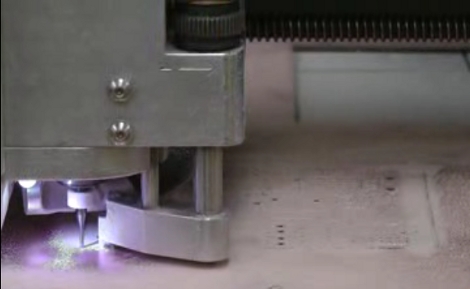
[Juan Jose Chong] put together a set of videos and a PDF guide to milling printed circuit boards. You’ll find the pair of videos, totaling about twenty-two minutes, embedded after the break. In them, [Jaun] details the techniques used by the IEEE chapter at Texas Tech University to mill PCBs instead of using the traditional method of etching them. We’ve long been a fan of milled PCBs and often dream about the day we can retire the old iron we use for the toner transfer method.
In the tutorial, IsoPro is the software used to control the mill. The CAM files from a PCB design program are imported – they can come from many different programs including EagleCAD. A few setup steps let the operator configure the resolution necessary to mill the correct tolerance and from there the paths that outline each trace are calculated in software. In order to facilitate double-sided boards a reference hole is drilled in the copper clad board to accept a post on the mill table. Tape down the substrate with some foil tape, set the depth of the end mill bit, and let the machine do its thing. [Juan’s] video illustrates how quickly this can produce a rather complicated board, finishing in around 20 minutes.


