Sometimes it seems like eBay is the world’s junk bin, and we mean that in the best possible way. The variety of parts available for a pittance boggles the mind sometimes, especially when the parts were once ordered in massive quantities but have since gone obsolete. The urge to order parts like these in bulk can be overwhelming, and sooner or later, you’ll find yourself with a fistful of old stuff but no idea how to put it to use.
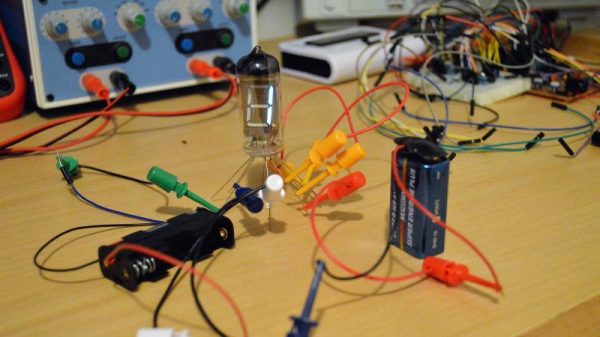
Case in point: the box of Russian surplus seven-segment vacuum fluorescent displays (VFDs) that [w_k_fay] had to figure out how to use. The result is a tutorial on quick and dirty VFD drivers that looks pretty handy. [w_k_fay] takes pains to point out that these are practical tips for putting surplus VFDs to work, as opposed to engineered solutions. He starts with tips on characterizing your surplus tubes in case you don’t have a pinout. A 1.5 V battery will suffice for the hot cathode, while a 9 V battery will turn on the segments. The VFDs can be treated much like a common cathode LED display, and a simple circuit driving the tube with a 4026 decade counter can be seen below. He also covers the challenges of driving VFDs from microcontrollers, and promises a full build of a frequency counter wherein the mysteries of multiplexing will be addressed.
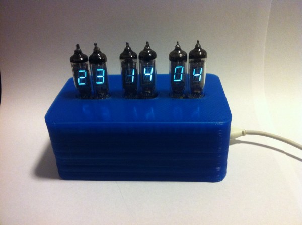
Sounds like it’s time to stock up on those surplus VFDs and put them to work. For inspiration, take a look at this minimalist VFD clock, or perhaps mix VFDs with Nixies to satisfy your urge for all things glowy.
Continue reading “Quick And Dirty Driver Tips For Surplus VFDs”