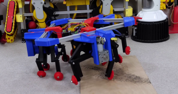
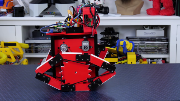
[James Bruton] is on a quest to explore all the weird and wonderful methods of robot locomotion, and in his latest project created an omnidirectional walker that can move in any direction instantaneously.
The walker actually makes use of three independent four-legged Strider mechanisms, connected in a triangle at 120deg. Wheels are attached to the bottom of each leg, oriented at a right angle to the leg’s plane of motion to allow the foot to slide. Varying the relative speed and direction of each of the mechanisms lets the robot move in any direction, similar to his ball-wheeled robot. Each strider mechanism uses a single motor and looks similar to Strandbeest walkers, but it lifts its feet to traverse rougher terrain. [James] demonstrates this with some obstacles, and found that moving in such an orientation that all three sets of legs provide the best results.
[James] planes to build a larger rideable version, but we think he should mount a chest of Sapient Pearwood to carry all his stuff and name it The Luggage.
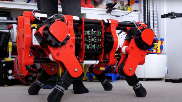
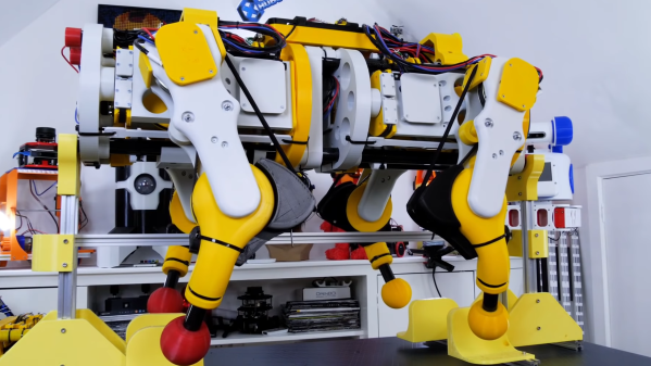
We’ve been following [James Bruton]’s open dog project for a little while now, and with his considerable pace of work – pandemic or no pandemic – development has been incredibly rapid. The latest milestone is the public release of version 3 (Video, embedded below.) This upgrade to the system adds 3D printed cycloidal gearboxes, removing the previous belt drives. [James] had immense fun tuning the motor controller parameters for these and admits they’re not completely dialed in yet. He notes that the wider gearbox body means that the robots geometry needed to change a little, and the previous belt-drive version may have a bit of an edge, but he’s confident he can make it work (and given his incredible previous robotics builds, we totally believe he’ll nail it!)
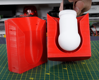
Silicone overmolding around a 3D printed former, using a 3D printed mould
Older versions struggled with slippery plastic feet; the advantage of a predictably smooth contact shape of a rounded foot is somewhat offset by the limited contact patch size, and that means not so much grip on some surfaces. [James] solution was obvious enough – just learn how to make 3D printed silicone moulds and cast a nice rubber foot around a plastic former, and problem solved! Unfortunately he neglected to add some recesses for a lever to get in between the mould halves, so it was a bit of a struggle to separate after curing. A beginner’s mistake that won’t be repeated, we’re sure.
Full source for openDogV3 is now available on the GitHub page. Here’s the playlist for the whole project, as well as direct links for the cycloidal drive development (part1, part2, part3.) But before you all go diving in to start 3D printing your own pooch, [James] tells us that the total cost would be around $2000 all in, with the bulk of that being the motors and ODrive units, so this one for the serious builder only!
We’ve covered robot dogs a fair bit, a particularly nice example is The Dizzy Wolf, and if you’re wondering just why on earth you’d want a robot dog, then Ask Hackaday has you covered as well.
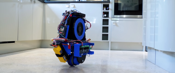
Self-balancing robots have become a common hobby project, and they usually require two wheels to work. [James Bruton] has managed to single wheel balancing robot by adding gyroscopic stabilization.
[James] has done other self-balancing robots, like his Sonic robot, but recently started experimenting with gyroscopic stabilization. In that project, he proposed the idea of combining the two stabilization methods to create a monowheel robot, and he followed through on that idea. The wheel is powered by a brushless motor and is stabilized conventionally around the wheel’s axis. Side to side balancing is achieved using a phenomenon known as gyroscopic precession, by tilting a pair of heavy spinning wheels. This is not to be confused with reaction wheels, which use rotational inertia for control. It appears the actuating the gyroscopes also affects the front-to-back stabilization, so at the moment the robots won’t stay on one spot. [James] plans to implement a second observation controller in software to solve this.
Another challenge with this robot is that it cannot turn at the moment. The gyroscopes are not in the correct orientation to effect rotation around the vertical axis, and changing their orientation would cause other problems. A fan, which works like a helicopter’s tail rotor is one option, and a reaction wheel on top might also work. We’re partial to the reaction wheel idea. Having a different mechanical control mechanism for each axis would make it quite an interesting robot.
Tracked robots usually require at least two wheels inside to work properly. However, [James Bruton] discovered a curious tractor design from the 1940s, the Fordson Rotaped, which only uses a single sprocket wheel inside each track. Being [James], he built a self-balancing robot around the rotaped concept.
Instead of a lot of short track sections, the Rotaped uses six long sections of track, about the same length as the wheel’s diameter. To keep the track on the wheel, a series of chains or an oval frame is used on the inside of the track.
As is usual for [James]’ projects, most of the mechanical parts are 3D printed. To hold the tracks in place, he stretches a bungee cord loop around three points on each side of the track. To make things more interesting, he made the robot balanced on the tracks. This took a bit of PID tuning to get working without oscillations, since the wheels experience a slight cogging effect inside the tracks. The wheels are driven by a pair of brushless motors with O-Drive controllers. The balancing is handled by an Arduino Mega, which reads processed position values from an Arduino Pro Mini connected to an MPU6050 IMU.
This might be a viable alternative to conventional tracks for certain applications, and the reduced part count is certainly an advantage. Let us know in the comments if it spawns any ideas. [James] has previously built another tracked rover, which uses flexible 3D printed track sections. By far, the biggest 3D printed tracked vehicle we’ve seen was [Ivan Miranda]’s ridable tank.
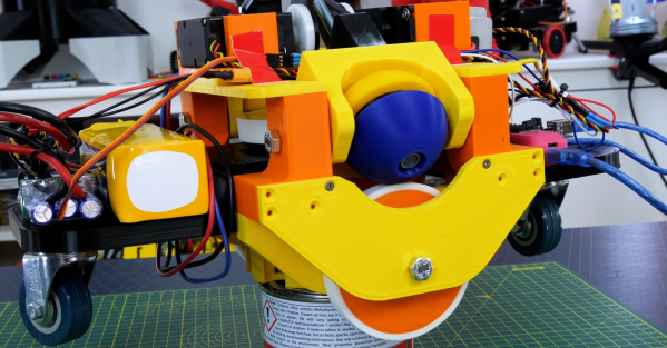
[James Bruton] is experimenting is a series of interesting mechanical mechanisms, the latest being a CVT transmission system which uses a tilting sphere to get a variable speed output from a constant speed input. Video after the break.
In [James]’ proof of concept RC vehicle, a single powered disc is mounted on top, at 90 degree to the wheels. A rotating sphere makes contact with both the driven disc and the wheel. When the rotation axis of the sphere is at 45° between the disc and the wheel, it provides a one 1:1 transmission ratio. As the axis is tilted, the contact points on the sphere shift, changing the relative circumference at the contact points, and therefore changing the transmission ratio. It can also reverse by tilting the sphere in the opposite direction, and disconnected from the output wheel by aligning it with the hole in the bottom of the sphere. [James]’ simple two-wheel RC car concept quite well, driving around his kitchen with the transmission spheres being tilted by servos.
Thanks to the response time, CVT gearboxes are generally not needed for electric motors, but on internal combustion engines that which run best within a certain RPM range they can be very useful. One possible weak point of a design like this is it’s dependence on friction to transfer torque, which makes it vulnerable to wear and slipping.
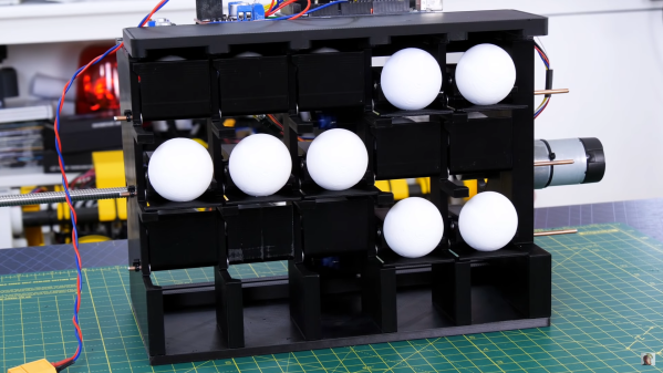
Flip dots displays are timeless classics, but driving the large ones can quickly turn into a major challenge. The electromagnets require a lot of current to operate, and the driver circuits can get quite expensive. [James Bruton] wanted to build his own, but followed a bit of a different route, building a mechanically multiplexed flip dot (ball?) display.
Each of the dots on [James]’ 5×3 proof of concept is a bistable mechanical mechanism that can either show or hide a ping pong ball sized half sphere. Instead of using electromagnets, the dots are flipped by a row of micro servos mounted on a moving carriage behind the display. The mechanism is derived from one of [James]’ previous projects, a mechanical multiplexer. Each dot mechanism has a hook at the back of the mechanism for a servo to push or pull to flip the dot. A major disadvantage of this design is the fact that the servo horn must match the state of the dot before moving through the hook, otherwise it can crash and break something, which also reduces the speed at which the carriage can move.
This build was just to get a feel for the concept, and [James] already has several ideas for changes and improvements. The hook design can certainly change, and a belt drive would really speed things up. We think this mechanical display is a very interesting design challenge, and we are interested to hear how our readers would tackle it? Let us know in the comments below.
Recently we covered a 3D printed flip dot display for the first time. It’s still small and [Larry Builds] is working out the kinks, but we would love to see it eventually match the mesmerising effect of Breakfast’s large installations.
One of the challenges of many walking robot designs is the fact that they draw current just to stay upright. This was exactly the case for one [James Bruton]’s quadruped robots, where the knee motors were getting too hot to touch. Adding springs to take some of the load is not as simple it might seem, so [James] created a bungee assisted cam mechanism to do the job.
For a normal spring-loaded lever, force is proportional to how much the spring is stretched, which will require the actuators to draw more and more current as it lifts the leg higher. For the spring force to remain constant throughout the range of motion, the length of the lever arm must become continuously shorter as the knee is bent. [James] did this by stretching a bungee cord around a cam. The added bulk of the cam does however cause the knees to knock into each other in some scenarios, but [James] plans to adjust the robot’s gait to avoid this. He didn’t get around to actually measuring the current draw reduction, but the motor temperature has dropped significantly, only being slightly warm after a test run.